Basler DGC-2020 Digital Generator Set Controller
Basic Product Information and Security Standards
1 Applicable scenarios
Single emergency unit, multi unit parallel power station, mains power switching ATS system, ECU electronic control engine (MTU/Volvo/standard J1939 model), taking into account backup fire power supply (meeting NFPA10), and industrial continuous power generation.
2 Safety requirements
Only certified electrical personnel are allowed to operate; The entire machine must be grounded independently with 12AWG and copper wire;
Panel, remote communication graded password protection (OEM/SET/OP three-level permissions);
Prohibit direct measurement of controller terminals with a megohmmeter to avoid semiconductor breakdown of the board;
RTC backup battery specific model, mismatch will result in loss of warranty.
Version 3 iteration instructions (manual/firmware/software/hardware)
The K-version of the manual has added functions such as 51-3 overcurrent components, reactive power/power factor control, offline phase reversal, and shutdown cooling;
BESTCOMSPlus has added Chinese and Spanish interfaces, and improved the ECU and expansion module configuration interface;
The firmware has added multiple alarms, multiple fixed value logic, and load sharing matching parameters;
Hardware iteration optimization of LCD heating, CAN bus, and terminal reliability.
4 model codes (Style codes distinguish hardware configurations)
Coding segmentation definition: CT acquisition 1A/5A, frequency 50/60Hz, output contacts A (4 channels)/B (12 channels), whether equipped with RTC battery, automatic synchronizer RS485、 Built in dial-up Modbus and LCD heater;
Special order models support Class I Div2 explosion-proof certification for hazardous areas.
5 Core Electrical Hardware Specifications
power supply system
12/24V DC wide power supply, capable of withstanding startup voltage drop to 0V and maintaining operation for 50ms; RTC clock capacitor backup, optional BR2032 lithium battery with a lifespan of 10 years.
Collection circuit
Voltage acquisition: 12~576V line voltage, supports three-phase/single-phase, PT ratio adjustable from 1 to 125;
Current acquisition: available in both 1A and 5A CT hardware versions, with a secondary short-time withstand of 10 times the rated value;
Engine sensing: oil pressure, water temperature, fuel level analog transmitter input, MPU magnetic pulse speed measurement;
CAN J1939 bus: directly reads ECU speed, exhaust temperature, and fault code DTC, without the need for a separate transmitter.
Switching IO (main body)
1 dedicated emergency stop normally closed input+16 programmable dry contact inputs;
Fixed output: preheating, starting motor, fuel solenoid valve;
Programmable output of the main body: Type A with 4 contacts (Type A code)/12 contacts (Type B code), with a single 30A short-time on-off capacity.
Communication interface (standard/optional)
Front end Mini-B USB: local PC debugging, firmware upgrade;
Backplane CANbus: connects LSM/CEM/AIM expansion modules and engine ECU;
Optional RS485: Modbus RTU, networked SCADA;
Built in dial-up Modbus (optional): automatically dials 4 sets of paging numbers in case of faults;
LSM load sharing module expands Ethernet remote access.
Environment and Certification
Working temperature -40 ℃~70 ℃, storage -65~85 ℃; Passed UL/CSA, CE, NFPA10, explosion-proof selection certification; Through impact, vibration, static electricity, and fast pulse EMC testing.
Panel HMI Human Computer Interaction System
1 panel hardware components
LCD backlight display, Auto/Run/Off three mode key, reset key, mute key, light check key, four-way navigation+edit key;
Status LED: Non automatic, alarm flashing, on load operation indicator light.
2 Display Function Configuration
Two homepage modes: fixed streamlined display, scrolling custom screen (up to 20 parameters can be freely configured);
Phase automatic rotation with adjustable delay, supporting Chinese English/Spanish;
Sleep energy-saving: Turn off backlight and heating for 15 minutes without operation, and do not sleep in alarm state;
Permission control: During remote communication, the panel is only read-only, and modifying parameters requires logging in with the corresponding password.
Three main branches of the menu
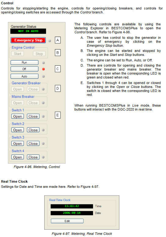
Metering Menu
Engine (oil pressure/water temperature/speed/running time), generator (three-phase voltage/current/frequency), power (kW/kVA/kVar/power factor), alarm status, event log, ECU fault code, synchronization status, and data collected by the expansion module.
Settings menu
Universal, communication, system parameters, programmable IO, alarm, generator protection, circuit breaker, synchronous voltage regulation and speed bias, multi unit parallel logic, BEST logic, clock time zone daylight saving time.
4 Remote optional RDP-110 display units
Independent remote control panel, connected through a dedicated bus, remotely displays all pre/fault alarms to meet remote monitoring of the computer room.
Core functional modules of the whole machine
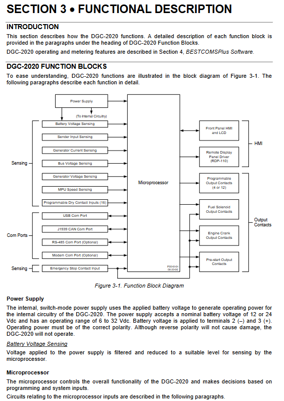
1. Power supply and microprocessor architecture
Switching power supply is compatible with wide DC, and multiple ADCs are used to collect all analog signals; Hardware watchdog prevents program crashes and zero crossing detection calculates frequency.
Two major operating modes
OFF mode: Automatic start is prohibited and can only be manually stopped locally;
RUN manual mode: continuous operation, not controlled by the automatic start stop logic of mains power/load;
AUTO automatic mode: fully automatic logic (starting from mains power failure, starting and stopping according to load demand, timed machine testing);
Shutdown cooling mode: After unloading and opening, the no-load delay cooling is applied to protect the turbine unit.
3 Complete Engine Control Logic
Preheating output: Delay preheating plug before startup;
Start logic: cycle start (up to 7 times)/continuous start, choose one, can be determined by oil pressure/speed to disconnect the starting motor;
Automatic restart: Fault shutdown delay retry, limit the number of starts;
Timed trial operation Exercise: start and stop on a daily/weekly/monthly basis, and can operate with load;
J1939 ECU linkage: reads all operating parameters and DTC fault codes of the engine, and can pulse wake up the ECU to collect data.
Automatic switching function of ATS mains power supply
Detecting three-phase mains undervoltage, frequency loss, and power outage to determine mains faults;
Delay starting the unit after the fault, and close the generator circuit breaker for stable power generation; After the restoration of mains power, disconnect and unload, delay the switch back to mains power, and support open conversion without grid connection.
5 Circuit Breaker Management System
Control the mains switch and generator switch separately, and verify the closing conditions:
Turn on the generator switch: Close the no-load dead bus directly; The live busbar must perform automatic synchronization;
Synchronizer function: automatically adjust AVR voltage regulation, speed regulator speed up and down, match voltage frequency phase, capture synchronization angle closing;
Fault alarm for opening and closing, pre alarm for synchronization failure.
6 sets of ANSI standard protection for generators (standard/enhanced hardware differentiation)
|Protection Number | Function | Action Logic|
|27 undervoltage/59 overvoltage | machine terminal voltage exceeding limit | pre alarm/shutdown trip, frequency lockout can be set|
|81U low frequency/81O high frequency | abnormal frequency | overload low frequency load reduction protection|
|32 reverse power | generator reverse active power | prevent the unit from being dragged by the mains power|
|40Q demagnetization | Low reactive power, demagnetization protection|
|47 three-phase imbalance | phase to phase voltage imbalance (enhanced type)|
|51 inverse time overcurrent (3 groups) | Multi segment current protection, built-in 16 international standard inverse time curves|
All protections can be set with pick-up values, delay, pre alarm/shutdown actions, and support low load scaling.
7 Measurement and statistical functions
Real time three-phase active power, reactive power, apparent power, and power factor;
Accumulated operating hours, loaded/unloaded duration, number of starts, maintenance countdown;
Continuous monitoring of oil pressure/water temperature/fuel level, transmitter disconnection alarm.
8 Event Recording System
Non volatile storage for 30 types of events, with a maximum of 99 records per type, each with date, time, and engine hours; Record protection actions, IO displacement, communication failures, module disconnections, synchronization failures, etc., which can be read from the panel or exported through software.
9 Programmable IO and Bias Control
16 local inputs+CEM extended inputs, capable of mapping functions such as mains power detection, fault lockout, overload shielding, single-phase forced mode, etc;
Output controllable circuit breakers, alarm speakers, AVR voltage regulation bias, and governor speed regulation bias;
The supporting LSM module can achieve constant reactive power/constant power factor, multi unit reactive power sharing, and active load distribution.
Three optional expansion modules (CAN bus communication)
1 LSM-2020 Load Sharing Module
Core used for parallel connection of multiple units:
Simulate output regulation of AVR and speed regulator to achieve active/reactive power balance;
Built in Ethernet, supports BESTCOMSPlus remote networking debugging;
Sequential start stop of multiple units, automatic increase or decrease of load demand for units;
Monitoring module loss, ID duplication, bias output limit alarm.
CEM-2020 Contact Expansion Module
CAN bus expansion IO: adding 10 inputs and 24 relay outputs for multiple circuit breakers, remote alarms, and auxiliary control.
3 AEM-2020 Simulation Expansion Module
8 channels of 4-20mA/0-10V analog inputs, 8 channels of RTD platinum resistors, 2 channels of thermocouples, and 4 channels of analog outputs; Used for collecting water temperature, exhaust, fuel tank, and bus transmission data, and outputting external recorders.
BESTCOMSPlus upper software
1. Software Fundamentals
Windows platform, relying on NET framework, free DGC-2020 plugin, supports offline parameter editing, online reading and writing, firmware upgrade, event export, and parameter comparison.
2 Communication methods
USB local direct connection: debugging, flashing firmware;
Modbus RS485: Industrial SCADA networking;
LSM Ethernet remote: centralized management of multiple controllers in a local area network;
Dialing modem: Remote telephone dialing monitoring alarm.
3 Software Core Function Blocks
Set up browser: complete set of parameters visualization configuration for the whole machine, communication, engine, protection, logic, and expansion modules;
Real time monitoring browser: All battery levels, engines, alarms, and IO are refreshed in real-time;
3 Bestlogic drag and drop programmable logic;
File management: save/export/print fixed values and event logs;
Remote upload and upgrade of firmware and language packs;
Unified configuration of clock, time zone, and daylight saving time.
4 Permissions and Security
Three level password partition management, which can lock parameter modification and firmware flashing permissions; All modification operations are recorded in the audit log.
BEST Logic+Programmable Logic
Visual drag and drop programming, no code required:
Component library: protecting components IO、 Timer, circuit breaker, synchronization, bias, and expansion module points;
Boolean and/or/non, self-locking, pulse, and delay logic can be freely constructed;
Customize alarm, interlock, and pressure plate functions to replace traditional intermediate relays;
Logic can be uploaded and downloaded separately, supporting the reuse of engineering templates.
Installation, Wiring, and Maintenance
Installation: Standard panel holes, 4 fixing bolts, and reliable grounding of the metal shell;
Terminal differentiation: power supply, voltage CT acquisition, engine transmitter, CAN bus, communication, expansion interface;
Wiring requirements: Separate strong and weak electricity, and strictly prohibit open circuits in CT circuits;
Maintenance: Regularly tighten terminals, clean panels, and check RTC batteries;
Troubleshooting: Complete troubleshooting process for communication interruption, protection misoperation, inability to synchronize, startup failure, and missing expansion module.