Basler L301kc Color Three Line Array Camera Operation Manual
Core Hardware Specifications of the Whole Machine
1. Core parameters of sensors
Photo sensitive chip: Kodak three line color CCD (red/green/blue independent rows), with 2098 pixels per row;
Pixel size 14 μ m × 14 μ m, center to center spacing between rows 112 μ m, filling rate 100%;
Non uniformity: average light response<5%, maximum<10%; Typical dark signal ± 1DN (0dB gain);
The spectral response is 350-850nm. After 700nm, the filter becomes ineffective and must be paired with an infrared cut-off filter to ensure color.
2. Line frequency and pixel clock
Space correction: maximum line rate of 8.0kHz; Turn off calibration up to 9.2kHz; Minimum 1kHz;
Pixel clock is divided into three levels:
20MHz (8-bit RGB mode), 40MHz (dual pixel 8/10bit), 60MHz (single pixel 8/10bit).
3. Power Supply and Environment
Power supply: 12VDC ± 10%, overall power consumption<5.1W;
Working temperature: 0-50 ℃; Storage temperature -65~+85 ℃; Humidity of 20-80% without condensation;
Anti vibration and impact meet industrial standards, and the shell needs ventilation and heat dissipation to prevent high temperature burns.
4. Lens and Mechanical Fundamentals
Lens interface: F-port;
The shell is processed with high-precision flatness/parallelism, and M4 mounting holes are reserved on both the front and side surfaces.
Camera Interface, Cable, Hardware Circuit
1. Two types of interfaces (rear)
26 pin MDR Camera Link interface: transmits image data, RS-644 serial port, ExSync external trigger, Integrate exposure synchronization signal; Define LVDS differential signal pins;
6-pin Guangse miniature push-pull power socket: 12V DC input, reverse connection is strictly prohibited.
2. Supporting cable specifications
Camera Link data cable: original factory 3m/5m standard parts, maximum recommended length 10m; dedicated cable can lead out IntEn exposure signal;
Power cord: Double shielded twisted pair, up to 6 meters long, with the power end shielded and grounded.
3. Internal transceiver chip
Image sending DS90CR287, frame collector receiving recommended DS90CR288/288A; The serial port transceiver adopts DS90LV047A/048A differential chip and standard RS-644 (Camera Link built-in serial port).
4. Detailed explanation of input/output signals
Input signal: ExSync external trigger
Control line readout and exposure, divided into three exposure modes: edge/level/programmable; The signal must jump, with a minimum high level of 0.35 μ s.
output signal
Pixel Clock: Data sampling reference;
Line Valid (LV): a valid line identifier; Data Valid is equal to LV and has no independent effect;
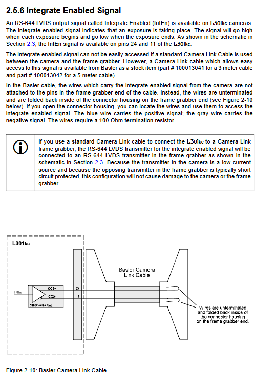
Integrated Enabled (IntEn): Exposure start stop differential signal, can be used for flash synchronization; Ordinary cables cannot be led out and require Basler dedicated wires.
5. Five major image output modes
Format Description of Pattern Pixel Clock Data
20MHz 8-bit RGB 20MHz single clock cycle simultaneously outputs 8-bit R/G/B, color native output
60MHz single pixel 8-bit 60MHz line by line sequential output of R/G single 8-bit
60MHz single pixel 10 bit 60MHz native 10 bit ADC output
40MHz dual pixel 8-bit 40MHz single cycle output with two sets of pixels, improving bandwidth
40MHz dual pixel 10 bit 40MHz dual channel 10 bit high-precision output
6. Serial communication RS-644
Standard 8N1 serial port, can be converted to RS232 for direct connection to a computer through a Basler k-BIC converter; Provide two sets of configuration methods for CCT+graphics tools and underlying binary instructions.
7. Rear status LED
It is normal for the orange light to remain on when powered on; When there is a fault, the red and green flashes alternately, and different flashing times correspond to different error codes.
Core Imaging Functions (Camera Internal Algorithms)
1. Working process principle
Three line CCD synchronous exposure, analog signal through independent VGA gain circuit and 10 bit ADC analog-to-digital conversion; Store in FIFO buffer, align the three color pixels through spatial correction, and output through Camera Link.
2. Expose two major working modes
(1) ExSync external trigger mode (standard for production line encoder)
Edge control: Full ExSync cycle exposure, rising edge readout;
Level control: Exposure during ExSync low-level phase only;
Programmable: Rising edge initiates exposure, with the duration set by the Timer1 register.
(2) Free Run (no external trigger)
Internal Timer1 (exposure duration)+Timer2 (line spacing) controls line frequency, supporting edge/programmable two sub modes.
Limitation: The total cycle must not be less than the minimum line cycle, and if it exceeds the limit, a line frequency overload fault will be reported.
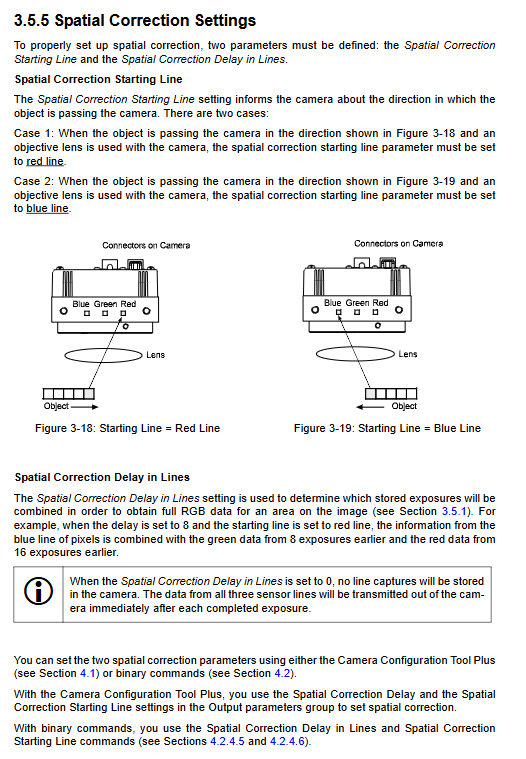
3. Spatial Correction (a core feature of this machine)
principle
The physical interval between R/G/B photosensitive lines is 112 μ m. Moving objects at the same position will be captured by the three color lines three times, and direct output will result in color trailing/edge (halo); The camera has a built-in FIFO buffer for multiple lines of data, aligning RGB according to the set offset to eliminate color difference.
Use mandatory conditions
Only 8-bit output mode is available, 10 bit automatic calibration is turned off;
The encoder must be triggered line by line and the conveying speed must be stable;
The sensor must be perpendicular to the conveying direction and parallel to the object surface, and a telephoto lens is recommended;
Two key parameters need to be configured:
Correction delay line count: The number of encoder steps required for an object to move across three color lines (1-16);
Starting line: When an object passes through a red line, set it as Red; when it passes through a blue line, set it as Blue.
Calculation formula for supporting system
Provide standard calculation formulas and engineering examples for magnification, field of view width, and image aspect ratio.
4. Gain and Offset (white balance adjustment)
Three color channel independent adjustable gain: 96 (0dB)~1023 (33.6dB); Gain boosting synchronously amplifies noise;
Adjustable offset from 0 to 255, used to lower the dark level;
It is recommended to prioritize adjusting the light source/exposure and avoid using high gain.
5. Digital Shift
The 10 bit raw ADC data can be shifted to the left by 1/2/3 levels, with equivalent amplification of 2/4/8 times; There is a saturation limit, and high shift is prohibited in strong light scenes. There are two sets of shift rules and usage restrictions for 8/10 bits.
6. AOI regions of interest
Can capture the output of specified pixel intervals in each row, reducing data volume but not increasing the maximum line frequency; Configure two parameters: starting pixel and output length.
7. Six sets of built-in test diagrams (fault diagnosis)
No optical imaging, directly output standard gradient image, used for troubleshooting cables, acquisition cards, and communication faults:
Grayscale gradient; 2. Move vertical grayscale; 3. Horizontal movement (verification of spatial correction); 4/5/6 single red/green/blue gradient;
Usage restriction: Space correction and shift functions are disabled when opening the test chart.
8. Parameter configuration set (non-volatile storage)
Three types of parameter groups are permanently stored in the camera EEPROM:
Work Set (RAM temporary current parameter, lost during power outage);
Factory Set (factory default, read-only and cannot be changed);
15 sets of User Sets (user-defined parameters that can be saved and loaded upon startup);
Support setting default loading group upon startup.
9. Camera self detection
Real time monitoring of line frequency overflow, FPGA faults, EEPROM checksum errors, serial port instruction errors, etc. The status can be read through tools/binary instructions, and the rear LED synchronously flashes with errors.
Camera Configuration: CCT+Graphics Tools+Bottom level Binary Instructions
Option 1: CCT+Visualization Software (Windows)
Basler official graphics configuration tool, connected to the camera via RS-644 serial port; Function: Visualize the modification of all parameters, save user configurations with one click, export parameter files, and automatically generate underlying instructions; Support online refreshing of real-time camera status.
Option 2: Binary serial port underlying instructions (for secondary development)
1. Communication frame standard
Frame structure: STX start (0x02)+descriptor+data+BCC XOR check+ETX end (0x06ACK/0x15NAK); Small end byte order;
Verification rule: The descriptor+data XOR is used to obtain the BCC verification code, and an error is returned as NAK.
2. Complete instruction set (read and write separated)
Covering all hardware functions:
Exposure mode Timer1/Timer2、 Space correction parameters, digital shift AOI、 Tri color gain/offset, output mode, test chart, camera reset;
Read commands: firmware version, serial number, model, internal temperature, machine fault status, serial port baud rate;
Storage class: Copy working set/user set, set boot configuration group;
Serial port baud rate modification instruction (default 9600, restart to restore default).
Each instruction provides an ID, data length, read-write identifier, value range, and practical examples.
Mechanical Dimensions and Installation Specifications
Millimeter drawing of the whole machine: length, width, and thickness, M4 installation hole positions on the front/side;
F lens mount size;
CCD chip positioning tolerance (translation and rotation accuracy);
Installation warning: Immediately install the lens after unpacking to avoid sensor dust accumulation.
Complete Troubleshooting Manual
Tree based troubleshooting process for four major types of faults, accompanied by a list of repair information collection:
No image: sequentially investigate power supply, LED error, ExSync trigger, timing parameters, acquisition card, and cables;
Poor image quality (all black/all white/noise/color halo):
Color edge halo → spatial correction parameters/installation verticality/abnormal conveying parallelism;
High noise → high temperature, long exposure, high gain, AC light source;
Overexposure/underexposure → aperture, exposure, gain adjustment;
Hardware interface failure: Camera Link cable, capture card configuration file, hardware replacement positioning;
RS-644 serial communication failure: serial port parameter 8N1, software port occupation, cable failure;
Quick lookup table for LED fault flashing codes
3 flashes=no ExSync trigger; 5/6=configuration set read/write failure; 7=FPGA instruction error; 8=FPGA loading failed; No lights=insufficient power supply.
Essential documents for repair reporting
Camera ID, serial number, capture card model, CCT version, detailed fault description, current parameter file, fault screenshot/test chart.