Basler AVC63-12/AVC125-10 excitation voltage regulator
Basic principles of product operation
AVC63-12 and AVC125-10 are used for stabilizing the excitation winding of synchronous generators
Collect the single-phase/three-phase output sampling voltage of the generator, compare it with the internal reference, and generate an error signal;
Error signal controls DC excitation output, dynamically adjusts excitation current, and stabilizes terminal voltage;
Integrated with multiple standard functions: V/Hz frequency compensation, inverse time limit over excitation protection, residual voltage excitation, parallel differential adjustment, line voltage drop compensation, auxiliary signal input interface, can be paired with reactive power controller, excitation current limiter and other external devices for linkage.
Complete electrical technical specifications
1. Power input (taken from the PT/PMG permanent magnet generator)
Supports single-phase/three-phase, compatible with 50/60/400Hz intermediate frequency units
Parameter AVC63-12 AVC125-10
Rated input voltage 90~153Vac 180~264Vac
Continuous maximum capacity 1092VA 1750VA
2. Voltage sampling circuit
Single phase/three-phase options are available, with a load of less than 1VA per phase; the sampling voltage is divided into two levels: 90~139Vac/180~264Vac.
3. Excitation power output (F1+, F2-)
Parameter AVC63-12 AVC125-10
Continuous excitation 12Adc@63Vdc 10Adc@125Vdc
10 second short-term strong excitation 24Adc@125Vdc 20Adc@250Vdc
The minimum resistance of the excitation winding is 5.25 Ω and 12.5 Ω
4. Core control performance indicators
Voltage regulation accuracy: set value ± 0.5%;
Temperature drift: Only ± 0.5% voltage deviation due to a temperature difference of 40 ℃;
Response speed:<4ms;
Residual voltage excitation: AVC63-12 minimum 6Vac, AVC125-10 minimum 12Vac;
Parallel Differential Power (DRP): 0~10% adjustable rated current (0.8PF);
Line voltage drop compensation LDC: CT reverse wiring enabled, only compensating for inductive line voltage drop;
Auxiliary input terminal 2/3: ± 3Vdc analog signal, connected to SCP250 reactive power controller and EL200 excitation limiter.
5. V/Hz low-frequency frequency compensation
Jumper second slope: 1PU V/Hz, 2PU V/Hz;
Adjustable turning point: 45~65Hz for 50/60Hz models, 300~430Hz for 400Hz models;
When the unit slows down, it automatically lowers the excitation to prevent overspeed and overvoltage.
6. Inverse time limit overexcitation shutdown protection
The higher the output voltage, the shorter the protection action time:
AVC63-12: Shutdown at 125Vdc for approximately 10 seconds, 210Vdc ≤ 1 second;
AVC125-10:250Vdc shuts down for about 10 seconds, 370Vdc ≤ 1 second;
Over time excitation output zeroing protection excitation winding.
7 Electromagnetic Compatibility and Safety Certification
Certification: UL508, CSA, CE;
EMC: Radiation/Conducted Emission Class A, 4kV Contact/8kV Air ESD, 2kV Electric Fast Pulse, Power Frequency Magnetic Field Immunity;
Type test: three-axis 20G impact, 18~2000Hz 4.5G vibration;
Environment: Working/Storage -40~70 ℃, maximum 95% non condensing humidity.
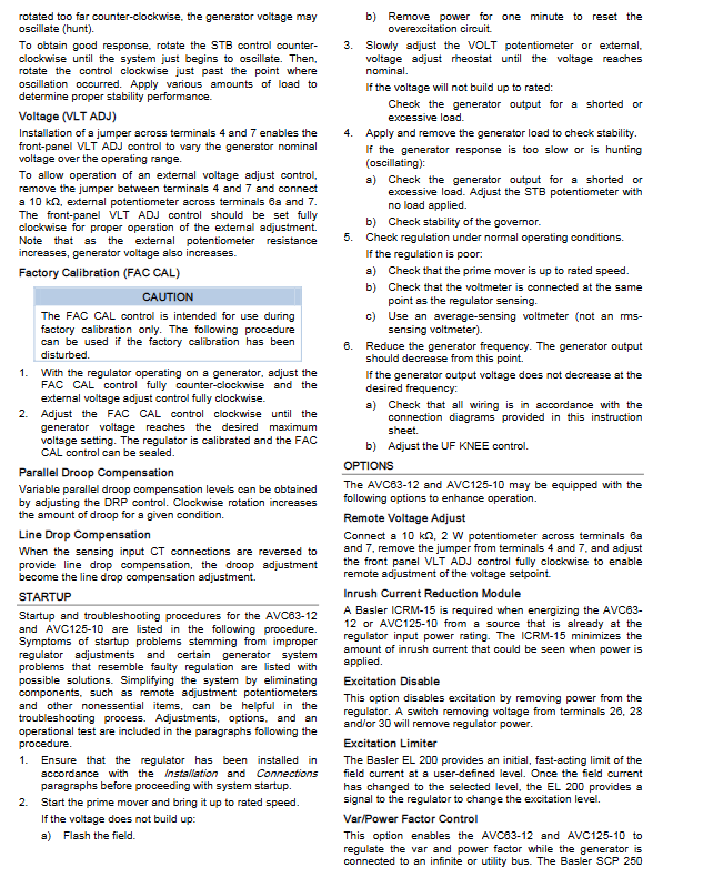
Hardware Terminal Definition (Upper and Lower Terminal Blocks)
Upper control terminal
1 CH GND: protective ground of the chassis
2. 3: Auxiliary analog input (connected to SCP250/EL200)
4. 7: Built in voltage regulating potential short circuit; Disconnect the external 10k Ω remote potentiometer
5/5a: 1A/5A current transformer CT common terminal
6. 6a: Functional common jumper terminal
8: Jumping to 6a → 1PU V/Hz slope; Not connected to 2PU
9: Reserved
20/22/24: A/B/C Three phase voltage sampling
26/28/30: Single phase/three-phase power input (PMG/PT power supply)
Lower power terminal
F1: Excitation positive pole output; F2: Excitation negative output
Key requirements for wiring
The secondary side of the voltage/current transformer is grounded at a nearby single point, and multiple CTs are only allowed to be grounded at one point.
All adjustable potentiometers and setting steps
1. VLT ADJ reference voltage
Short circuit 4-7 to enable panel knob; Disconnect and connect an external 10k Ω remote potentiometer (the higher the resistance, the higher the voltage).
2. UF KNEE low-frequency inflection point setting
Rated frequency operation of the unit;
Rotate counterclockwise to the end and adjust the voltage to the rated level;
Rotate clockwise until the voltage starts to drop, then retrace until the voltage recovers, and the inflection point is set.
3. STB stability (damping)
No load debugging: counterclockwise acceleration response is prone to oscillation, clockwise deceleration; Adjust to slight oscillation first, then reverse and eliminate, and retest with load.
4. DRP parallel differential adjustment
Clockwise increase the reactive power adjustment difference and evenly distribute reactive power among multiple machines in parallel; CT reverse connection switch to line voltage drop compensation.
5. FAC CAL factory calibrates potentiometers
Only for factory use, no arbitrary adjustments are allowed on site; After offset, the maximum output voltage can be recalibrated.
Field flashing operation for excitation and magnetization
Operation can only be carried out when the unit is shut down, and magnetizing during operation will burn out the regulator:
DC power supply within 24V connected in series with current limiting resistor (1 Ω/1V, such as 24V with 24 Ω/24W);
F1 connected to+, F2 connected to – power on for 10 seconds;
No boost, switch power polarity and retry;
Suitable for scenarios where the residual voltage of the generator is insufficient and it cannot self excite.
Optional supporting expansion module
ICRM-15 surge suppression module: reduces power on surge current;
EL200 excitation current limiter: quickly limits the maximum excitation current and sends the signal to the AVC auxiliary terminal;
SCP250 reactive power/power factor controller: ± 3V signal correction voltage regulation setting, grid connected unit controls reactive power;
CBS212 current enhancement system: Instantaneous strong excitation during short circuit/motor start-up to enhance voltage support;
MVC-112 manual excitation controller: standby manual voltage regulation in case of AVR failure or debugging.
Installation, testing, and maintenance
1. Mechanical installation
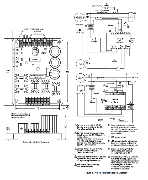
Epoxy resin encapsulated whole machine, installed at any angle; Using 1/4-20 bolts with a torque of ≤ 7.34N · m; accompanied by overall dimensional drawings.
2. Factory functional testing circuit
External indicator light load, verify the voltage regulation output function by adjusting the VLT ADJ to observe the light on and off.
3. Maintenance requirements
Regularly clean dust and moisture, and tighten all wiring terminals; It is recommended to first disconnect the remote voltage regulator and auxiliary peripherals to simplify the system positioning problem for troubleshooting.
Start up and troubleshooting process
Typical faults and their handling
Unable to start excitation and boost voltage: stop and magnetize; Power off for 1 minute to reset over excitation protection; Check that there is no short circuit in the excitation circuit;
Voltage cannot reach the rated value: check if the sampling wiring and load are short circuited;
Unstable voltage oscillation: Reset the STB stability knob and check the prime mover speed controller;
After slowing down, the voltage does not decrease: readjust the UF KNEE inflection point and check the V/Hz jumper;
Frequent tripping due to overexcitation: Check for short circuits, heavy loads, and short circuits in the excitation winding.