Basler BE1-27/BE1-59/BE1-27/59 undervoltage/overvoltage relay
General Basic Information
1. Product positioning and application scenarios
All three are solid-state voltage monitoring and protection relays that collect PT secondary voltage. After the voltage deviates from the set threshold, they delay the output of trip/alarm contacts. The five typical applications are:
Motor Protection
Undervoltage (BE1-27): Voltage drop, motor startup failure, overload, delayed tripping to avoid short-term voltage drop misoperation; Overvoltage (BE1-59) prevents winding insulation breakdown and flashover grounding.
Automatic switching ATS control
Main power supply undervoltage delay switching to backup power supply; Restore overvoltage monitoring of the main power supply and smoothly switch back to mains power.
Distributed cogeneration (grid connected anti islanding)
The islanded boosting of the external power outage unit and the 27 undervoltage blocking of the substation reclosing; Simultaneously monitor overvoltage (reactive capacitor switching boost) and quickly disconnect the generator in case of a fault.
Transformer protection
The fault of the tap changer causes over excitation/under excitation, and the BE1-27/59 dual function achieves full range voltage protection.
High resistance grounding fault detection
Three phase three wire PT open delta connection captures zero sequence unbalanced overvoltage, which is an implicit grounding fault that cannot be detected by ordinary overcurrent protection.
2. Model and Style Encoding Rules
Complete identification of the whole machine=basic model+style number, with segmented definition of style code:
Sampling phase number, voltage range, power supply type, instantaneous/timed/reverse timed sequence, contact type, action indicator light, installation method (semi embedded/protruding).
Example: A3F-E1J-A0S1F represents single-phase sampling, 55~160Vac range, timed limit, 120Vac/125VDC power supply, two normally open main contacts, and internal latch indicator light.
3. Core electrical technical specifications
(1) Voltage sampling circuit
Applicable frequency 40~70Hz (universal for 50/60Hz systems);
Three adjustable acquisition ranges: 1~40Vac/55~160Vac/110~320Vac;
Each phase load is less than 1VA and can withstand up to 480Vac continuously;
Action accuracy: Setting value ± 2% or 0.5V (whichever is higher); The return value is ± 2% of the action point.
(2) Timing mode (optional for ordering)
Instantaneous type: voltage exceeding the setting by more than 5%, response<50ms;
Definite E1/E2: 0.0~9.9s, step size 0.1s, accuracy ± 2%/50ms; 0 gear equals instantaneous;
Inverse time limit (short/medium/long C3/C4/D3/D4): The larger the voltage deviation, the faster the action. The panel can be adjusted from 01 to 99 levels, and a complete set of UV/OV inverse time limit curves is attached.
(3) Output contact capacity
Communication 120Vac: continuous 7A on/off;
DC 250Vdc: short-time 0.2s 30A, continuous 7A, breaking 0.3A;
The inductive load breaking is only 0.3A (L/R=0.04);
Optional normally open NO/normally closed NC main contact, auxiliary contact, and power monitoring contact.
(4) Multiple specifications of power supply
DC: 24V (L), 48V (K), 125V (J/Y), 250V (Z); Communication at 120/240Vac; Wide voltage input, overall power consumption of 3.8~28.4VA.
Power monitoring contact: The normally closed point of normal power supply is disconnected, and it automatically closes when power is lost, used for device fault alarm.
(5) Action indication Target
Two types of red LED locks:
Internal drive: No need for circuit current, compatible with NC contacts;
Current driven: The trip circuit must be at least 200mA to light up, turn off when powered off, restore the locked state when powered on, and manually reset the panel.
(6) Environment, Machinery, and Certification
Anti impact three-axis 15G, 10-500Hz 2G vibration; 2kV power frequency withstand voltage;
Certification: UL508, Russian GOST-R;
The S1 shell of the whole machine weighs 6.35kg; there is no installation angle limit for solid state.
Front Panel Controls and Indicator Lights
All adjustable knobs and indicator components on the panel:
UV Pickup: Undervoltage Action Threshold Potentiometer
UV Time: Undervoltage delay (timed/inverse time)
UV Inst: Transient threshold for undervoltage
OV Pickup: Overvoltage action threshold
OV Time: Overvoltage Delay
OV Inst: Overvoltage instantaneous threshold
Red power LED: always on when powered on
UV/OV Action LED: Illuminates when voltage exceeds limit
Target reset button: Clear latch fault light
Hidden test button: non-metallic rod press manual drive output contact verification circuit
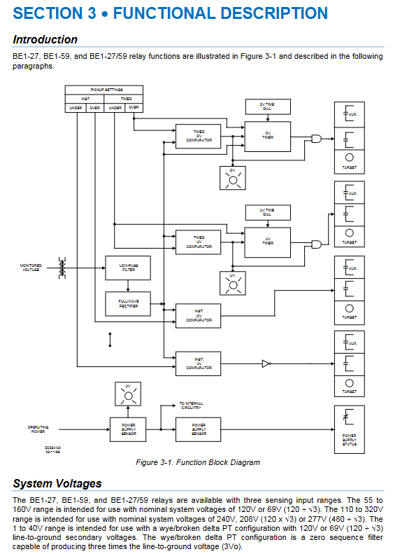
Internal Functional Principle Block Diagram
Signal Link
PT voltage reduction → low-pass filtering (suppressing high-frequency interference above 226Hz) → full wave rectification, converting AC to DC amplitude signal and sending it to multi-channel comparator.
Comparator grouping: four independent comparison units for under voltage instantaneous, under time limit, over voltage instantaneous, and over time limit. The logic priority for under voltage in BE1-27/59 is higher than that for over voltage.
Timing unit: Start timing after detecting the limit signal, and only drive the output relay when the set duration is reached; The inverse time limit dynamically shortens the action time based on the magnitude of the voltage deviation.
Output classification: main trip contact, auxiliary alarm contact, power monitoring contact, test drive circuit.
Latch indication: After the fault contact is closed, the LED will lock and temporarily disappear when powered off. When powered on again, the fault indication will be restored.
Installation, Wiring, Storage and Maintenance
1. Installation method
The S1 shell supports two types of panel installations: semi embedded and protruding, with accompanying perforated and three view drawings; There is no mandatory requirement for vertical installation in solid-state structures.
2. Key requirements for wiring
Main line ≥ 14AWG, grounding ≥ 12AWG independent ground wire;
2 PT secondary side is grounded at a nearby single point, and multiple sets of transformers are grounded at only one point;
During the voltage withstand test, it is necessary to pull out the terminal base and the core to prevent damage;
Provide a complete set of standard wiring diagrams for single-phase/three-phase AC and DC tripping, distinguishing between 27 undervoltage, 59 overvoltage, and 27/59 integrated machine terminal definitions.
3 Maintenance and Storage
No regular maintenance, only regular functional verification of the entire machine; The fault cannot be repaired on site, and the entire machine needs to be replaced;
Idle spare parts are powered on for 30 minutes every year to extend the lifespan of electrolytic capacitors;
Store in dust-proof and moisture-proof containers, and transport in original factory packaging boxes.
Standardized Whole Machine Testing Process
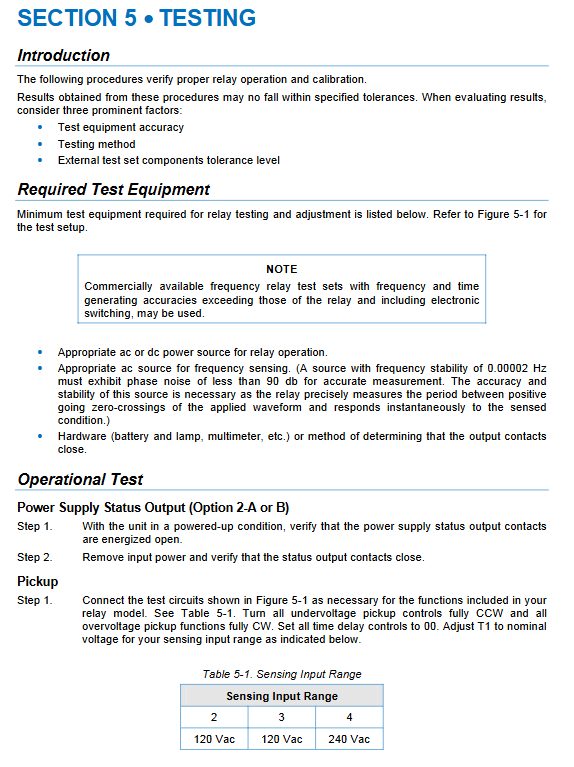
It includes three types of testing steps: power supply monitoring, action value (Pickup), and delay. It is accompanied by a dedicated testing circuit diagram and provides qualified intervals and timing error standards for each voltage range
Power monitoring test: power-off verification of contact closure;
Undervoltage/Overvoltage Action Value Verification: Slowly increase and decrease the voltage to record the trigger point, matching the ± 2% accuracy requirement;
Instantaneous/timed/reverse timed sequential testing: Verify the duration of the 00, 01, and 99 gear actions respectively, and compare the error range of the curve.