Beckwith M-3425A Generator Integrated Protection Device Manual
Product positioning and standard/optional hardware modules for the entire machine
1. Standard hardware configuration of the whole machine
Signal acquisition: 5 voltage inputs, 7 current inputs, supporting 1A/5A CT secondary specifications;
I/O basics: 6 programmable state inputs, 8 standard outputs (6 normally open+2 conversion contacts);
Communication interfaces: front panel RS232, back panel RS232, RS485; Standard COMTRADE/BECO waveform recording, capable of storing 416 cycles of fault data;
Event records: 32 fault action records with time stamps, 512 SOE event logs;
Measurement function: Real time measurement of three-phase voltage/current, sequence components, active/reactive/power factor, impedance;
Self diagnosis, IRIG-B clock synchronization, 4 independent constant value switching areas.
2. Optional extension accessories
M-3931 HMI human-machine interface: 2-line 24 character LCD panel, local setting of three-level permission password;
M-3925A Target fault indicator module: 24 protection action LEDs, visually distinguish fault types;
M-3921 excitation grounding coupler: equipped with 64F/64B rotor grounding and brush shedding protection;
Extended I/O: Extra 8 inputs+15 outputs (only available with IPScom software configuration);
Redundant power supply, RJ45 Ethernet (supporting Modbus TCP/IEC 61850);
Supporting tools: IPScom configuration software, IPSplus waveform analysis software, 20Hz low-frequency injection complete set of peripherals (signal generator, bandpass filter, dedicated CT, used for 64S stator 100% grounding protection).
3 Mechanical, Environmental, and Power Supply Specifications
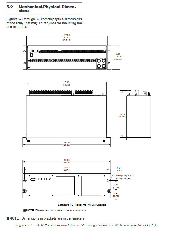
Installation: Standard 19 inch rack, available in both standard and extended I/O heights, supporting horizontal/vertical cabinet installation; Provide opening size drawings;
Environment: Operating temperature -20 ℃~+70 ℃, storage -65~+100 ℃; Resistant to vibration and impact in accordance with IEC 60255;
Power supply: Wide AC/DC dual specifications (AC110/120/230V, DC24/48/125/250V), dual power supply for extended I/O models;
Safety regulations: UL508, CE, CSA certification, insulation withstand voltage, static/electric fast pulse surge meet EMC standards for power equipment;
Contact capacity: The tripping contact can be connected for a short period of 30A, with a continuous load capacity of 8A. The inductive load breaking capacity complies with ANSI C37.90.
Classification of Three Major Function Software Packages (Core Protection Function Classification)
(1) Base Package (standard for all models)
Covering conventional electrical fault protection for generators, including ANSI standard components:
24 Extreme Magnetic V/Hz Protection (Time Limit+Inverse Time Hyperbolic)
27 Three phase undervoltage (three-stage fixed value independent delay)
32 directional power (reverse power/low forward power/overload three levels, can be used for shutdown interlocking)
40 demagnetization protection (double offset Mjolz impedance circle, with low voltage acceleration trip)
46 Negative sequence overcurrent (timed+inverse timed to prevent rotor overheating)
50 instantaneous phase overcurrent, 50N instantaneous neutral overcurrent
50/27 Non synchronous false closing protection (voltage loss lockout overcurrent)
50BF circuit breaker failure protection
50DT phase separated timed overcurrent (can be used as split phase differential)
51V with voltage control/voltage constraint inverse time overcurrent
51N inverse time neutral overcurrent
59 three-phase overvoltage, 59N neutral point overvoltage, 59X multifunctional turn to turn/bus overvoltage
60FL PT fuse fault detection (internal logic+external input dual-mode, automatic locking misoperation protection)
67N residual direction overcurrent (zero sequence grounding directional protection)
81 Four band frequency high/low protection
87 phase current differential, 87GD zero sequence ground differential
IPSigmic programmable Boolean logic (with/or/without+delay, custom interlock trip)
Circuit breaker wear monitoring BM, trip circuit monitoring TCM
(2) Comprehensive protection package (added on top of the base package)
21 Three section Mjolz phase to phase distance protection (system backup, with load shielding, out of step locking)
27TN Third Harmonic Neutral Point Undervoltage (High Resistance Grounding 90% Stator Grounding)
49 stator thermal overload I ² t protection
78 out of step/oscillation protection (three zone Mjolz+blocking characteristics, sliding pole counting)
81A low-frequency cumulative timing (to prevent resonance fatigue of turbine blades)
81R frequency change rate df/dt low-frequency load shedding
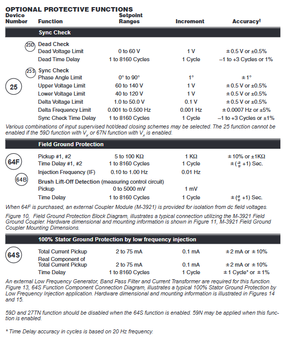
(3) Optional ordering of independent protection function (factory optional, cannot be added later)
25. Simultaneous inspection (pressure/frequency/phase locking, closing logic of thermal/cold busbar)
64F rotor excitation grounding, 64B brush detachment detection (M-3921 coupler required)
64S 20Hz low-frequency injection type 100% stator grounding protection (complete set of external signal equipment matching)
Principles and Key Points of Setting Range for Each Core Protection Function
1. Voltage protection (27/59/27TN/59D/59N/59X)
27/59: Three phase independent three-stage fixed value, supporting two sampling algorithms: RMS wideband/DFT fundamental wave;
27TN/59D: Utilizing the third harmonic voltage difference on both sides of the stator to achieve grounding protection for most windings of a high impedance grounded generator;
59X: Open triangle 3V0 voltage monitoring, used for stator turn to turn short circuit and busbar grounding;
64S: External 20Hz low-frequency injection into the stator neutral point, achieving 100% stator grounding under all operating conditions of generator grid connection/shutdown, compensating for the blind spot of third harmonic protection.
2. Power and demagnetization protection (32/40)
32 directional power:
Negative value=reverse power (to prevent the generator from being pulled back by the prime mover and the motor from running);
Positive values are divided into low active power and overload; The third component can switch reactive power monitoring;
40 demagnetization: Dual offset Mohorz impedance characteristics distinguish between light load/full load demagnetization, shorten trip delay under low voltage conditions, and avoid system absorption of a large amount of reactive power collapse.
3. Current differential and grounding protection (87/87GD/67N/50N/51N)
87 phase difference: percentage slope, supports CT ratio correction, main protection stator phase to phase short circuit;
87GD zero sequence differential: internal grounding protection for low resistance grounded units;
67N directional zero sequence overcurrent: distinguish between internal/system grounding to prevent external faults from tripping the generator;
4. Frequency protection (81/81A/81R)
81 Four segment high and low frequency alarm/trip;
Accumulate low frequency duration of 81A and calculate blade resonance damage;
81R frequency change rate, fast load switching.
5. 21 distance+78 step loss
Three segment Mohorz impedance, the third zone is specifically used for system power oscillation lockout, distinguishing permanent phase faults from synchronous oscillations to avoid step loss and false tripping.
6.25 Simultaneous Verification
Before closing, verify the voltage difference, frequency difference, and phase angle simultaneously; Supports multiple parallel logics for both empty and live busbars, and locks non synchronous closing.
7. 64F/B rotor protection
The coupler injects low-frequency signals into the rotor, measures the insulation resistance of the excitation to ground, and detects faults such as grounding of the excitation winding and disconnection of the carbon brush.
8. Auxiliary monitoring function
BM circuit breaker monitoring: integrate I ² t to calculate arc wear, reaching threshold alarm;
TCM trip circuit monitoring: detecting disconnection of trip coils and adhesion of contacts;
60FL PT disconnection: detects the melting of single-phase/two-phase/three-phase fuses, automatically locks voltage related protection (27/59/40, etc.);
IPSigmic custom logic: 6 independent logic units, which can achieve interlocking and automatic switching of fixed value groups through input, fault action, and timing combination.
Whole machine software and communication system
IPScom ® Upper software: Windows platform, supporting constant value reading and writing, real-time measurement, fault recording download, SOE viewing, and logic programming;
Communication protocol: Standard Modbus RTU/TCP, BECO2200, optional IEC 61850;
Time synchronization: IRIG-B modulation/demodulation signal, millisecond level time scale, unified time reference for faults, recording, and events;
Four fixed value zones: can be manually/HMI/external contacts/communication switched, suitable for unit grid connection/islanding, and different capacity operating conditions; The short-term locking protection of the switching process device is about 1 second.
Installation, wiring, and debugging chapter content
System single line diagram: Provide two mainstream CT wiring schemes: differential and split phase differential, with PT/CT, neutral point CT, synchronous voltage VX, and complete terminal connection of excitation coupler marked;
Terminal definition: Distinguish between voltage input, three-phase/neutral point current, control input, trip/alarm output, communication, and coupler specific terminals;
Grounding specifications: Independent thick copper wire for protective grounding, CT/PT secondary single point grounding, voltage withstand test requires unplugging the plug to avoid damaging the device;
Debugging process
1) System parameter input (CT/PT ratio, wiring method, phase sequence, transformer phase shift compensation);
2) Enable the required protection functions, allocate output contacts, and lock inputs;
3) Set various protection action values, delays, and curves;
4) Wave recording, event, clock configuration;
Standardization testing of the entire machine: Chapter 6 of the manual provides independent verification steps, testing circuits, and qualified accuracy standards for each protection, including self testing, analog calibration, and contact output testing.
Recording and diagnostic functions
Target fault storage: Save the last 32 trips, record the operating components, current and voltage, and time scale;
SOE event log: 512 millisecond level events, recording input displacement, protection start, trip, and communication status;
Fault recording: COMTRADE international standard waveform, can set trigger source (fault, external contact, communication command), pre recording+fault recording;
Device self diagnosis: power on self-test, real-time monitoring of CPU, memory, and peripherals during operation, flashing fault code LED prompt, complete fault code comparison table in the appendix.