Beckwith M-0359 Syncrocloser Check Plus Application Guide for Synchronous Calibration Relay
Basic Information
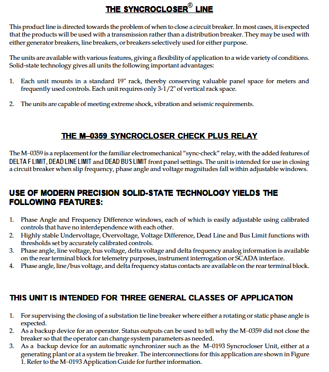
Product model: M-0359 Syncrocloser ® Check Plus synchronous verification device (synchronous locking relay)
Core purpose: To detect the voltage, phase angle, frequency difference, and voltage difference on both sides of the circuit breaker, and output a closing permission signal after meeting all thresholds; Support voltage loss closing (loss of bus/line), remote phase threshold switching, and SCADA analog telemetry output.
Product core positioning and three typical application scenarios
Applicable scenarios
Substation contact circuit breaker monitoring, suitable for power grid conditions with fixed phase/rotation frequency differences on both sides;
The backup verification of manually operated circuit breakers informs the reason for the fault that cannot be closed through status contacts;
The backup locking protection of automatic synchronization devices (such as M-0193) is used in series to enhance grid connection safety.
Core advantages of the product
Solid state precision circuit, independently adjustable with 6 sets of threshold knobs, no need for additional instrument on-site tuning;
0.5s fast phase detection, providing quick closing permission for power grid faults and islanding conditions;
Standardized DC analog output for all measurement quantities, compatible with mainstream SCADA remote control systems;
Support dual condition closing logic of static phase difference (ring network connection) and dynamic frequency difference (isolated grid generator);
Full circuit surge and transient overvoltage protection, meeting ANSI/IEEE C37.90.1 standard;
Wide temperature, moisture-proof and mildew proof PCB coating, suitable for harsh environments in substations.
Electrical input interface of the whole machine
1. Voltage sampling input (two isolated circuits)
Line side voltage, Bus side voltage: nominal 120V AC, long-term withstand voltage 145V AC, short-term withstand voltage 240V AC/1s; The two electrical circuits are completely isolated, and the power supply automatically takes the higher voltage side. If the voltage is lower than 65V, the whole machine will be locked and shut down;
Input load: 11VA on the high voltage side, only 1VA on the low voltage side.
2. Passive logic control input (dry contact)
Dead Line Close: Contact closure is enabled, and if the line voltage is below the threshold, the phase/frequency difference is ignored and the circuit is allowed to close directly;
Dead Bus Close: The contact closure is enabled, and the bus is directly closed when the bus loses voltage;
Restriction: Two circuits cannot be simultaneously closed due to voltage loss. At least one side of the circuit must have a voltage greater than 100V to output a closing relay;
Phase Angle Shift Phase Threshold Switching: Remote contact short circuiting can narrow/enlarge the allowed phase window, used for emergency expansion or normal strict grid connection;
The Sync Check Enable function is always enabled, and when disconnected, it locks all closing logic.
The front panel is equipped with independent adjustable knobs (all with scale calibration and do not interfere with each other)
Explanation of Parameter Adjustment Range and Accuracy Function
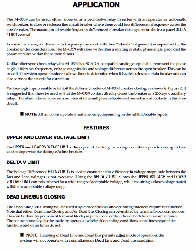
The upper limit of UPPER VOLTAGE LIMITED voltage is 110~140V ± 2% FS, and the line/bus voltage must not exceed this value
Lower VOLTAGE LIMITED Voltage Lower Limit 90~120V ± 2% FS Line/Bus shall not be lower than this value
DELTA V Limit Voltage Difference Threshold 1-5V ± 5% FS Upper Limit of Voltage Difference on Both Sides, Optional Other Range
DEAD LINE LIMIT Line Voltage Loss Threshold 10~60V ± 7% FS. If the FS is lower than this value, it is judged that the line has no voltage
DEAD BUS LIMIT Bus Voltage Loss Threshold 10~60V ± 7% FS. If the value is lower than this, it is judged that the bus has no voltage
The Phase Angle Limit allows for a phase angle of 0~± 30 °± 5% FS within the normal grid connected phase window, and supports remote scaling
DELTA F Limit Frequency Difference Threshold 0.01~0.5Hz ± 5% FS Upper Limit of Frequency Difference on Both Sides
Status indicator light (lit when all conditions are met)
The upper limit of bus voltage is OK, the lower limit of bus voltage is OK, the upper limit of line voltage is OK, the lower limit of line voltage is OK, the voltage difference is qualified, the line is live, the bus is live, the phase is qualified, and the frequency difference is qualified; Facilitate on-site intuitive judgment of the reason for closing and locking.
Classification of output circuits
1. Circuit breaker closing main relay (high-power dry contact)
Capacity: 250V DC can connect 20A; 120V DC inductive disconnect 0.9A, 250V DC inductive disconnect 0.4A; contact to ground withstand voltage 1500VAC/1min; Only when all voltage, frequency difference, and phase conditions are met simultaneously will it be closed.
2. Three sets of light load auxiliary relays (SCADA/local indicator lights)
Voltage status relay: both sides of the voltage are qualified and closed;
Phase state relay: The phase difference closes within the set window;
Frequency difference status C-type contact: frequency difference meets the standard and closes;
Rated: 125V DC resistive 0.5A, 120V AC 1A, used for background remote signaling and local alarm lights.
3. Standardized DC analog telemetry output (core SCADA function)
Can output 5 channels of DC analog signals, with two wiring schemes: voltage type and current type, equipped with anti reverse diode protection;
Remote measurement: bus voltage, line voltage, voltage difference on both sides, phase angle, frequency difference;
Range conversion standard (Table 1):
Phase angle: 0~± 180 ° → 10V DC/1mA full range;
Bus/line voltage: 0~150V → 7.5V/1mA;
Pressure difference 0~20V: 10V/1mA;
Frequency difference 0~0.5Hz: 10V/1mA;
The output range can be customized through an external resistor R3, with a maximum output current of 5mA.
Response timing performance
The initial power on voltage detection delay is about 0.5s;
Normal synchronization (with pressure closing): Complete phase, voltage, and frequency difference measurements in 0.5 seconds, and immediately output closing permission if conditions are met;
Bus loss/line loss closing mode: Ignoring phase frequency difference, output closing contact within 0.5s.
Hardware, Environment, and Protection Specifications
Hardware structure: 3 epoxy glass PCBs, sealed instrument level components for key components, precise resistance and capacitance to reduce drift; Optional M-0217 transparent protective cover to prevent knob misoperation.
Environmental indicators
Working temperature: -40 ℃~+80 ℃;
Humidity: up to 95% without condensation, PCB coated with anti mold layer;
Insulation anti-interference: All input/output withstand voltage to ground 1500VAC for 1 minute; Electrical isolation of each measuring circuit; By oscillating surges and fast transients according to ANSI standards.
Mechanical Installation
Standard 19 inch rack, occupying a height of 2U; Support installation inside horizontal/vertical cabinets;
Dimensions: width 48.3cm x height 8.9cm x depth 33cm; net weight 6.8kg, transportation 9.1kg.
Detailed explanation of core functional logic
1. Voltage loss closing (Dead Line/Dead Bus)
Enable through external contacts; When the voltage on one side is lower than the set voltage loss threshold, the system automatically shields the phase and frequency difference conditions and directly allows closing; Prohibit the operation of lines and busbars without voltage at the same time.
2. Remote phase window switching (Phase Shift)
Two typical uses:
Normal 15 ° window, island accident relaxed to 30 °: Normal contact closure reduces threshold, accident disconnection amplifies;
Normal strict 3 °, emergency expansion of the power grid relaxed to 15 °: remote contact closure expands the allowable phase.
The factory scaling ratio can be customized.
3. Frequency difference locking Delta F
Distinguish between isolated grid generators (with slip rotation phase) and ring networks (static phase), and directly lock and close them when the frequency difference exceeds the limit to prevent asynchronous impact.
4. Multiple voltage lockout (upper and lower limits+triple verification of voltage difference)
Not only is the voltage on one side qualified, but also the voltage difference between the two sides is constrained to avoid excessive voltage difference and surge current caused by grid connection.
Installation, tuning and maintenance specifications
1. Installation points
Reliable protective grounding of cabinet body; There is high voltage inside and outside the equipment, and only certified electrical personnel are allowed to operate it;
It is strictly prohibited to use in flammable and explosive environments; Do not open the cover when it is live, and fully discharge after power failure;
PT voltage transformer secondary open circuit is strictly prohibited.
2. Standard setting steps
Set the upper and lower limits of bus and line voltage;
Set the allowable pressure difference on both sides;
Configure the voltage threshold for lost lines/buses (enable as needed);
Set the logic to allow phase angle and remote scaling;
Set the maximum allowable frequency difference;
Check the panel indicator lights and verify the closing/locking logic of each operating condition.
3. Maintenance requirements
The circuit is precise, and on-site maintenance is not recommended. The faulty machine should be sent back to the original factory for inspection;
The equipment contains MOS chips, and the entire maintenance process is anti-static. It is prohibited to directly measure the resistance of the PCB board;
Damage to only the fuse is not covered by the warranty, and repair requires prepayment of shipping fees. Refusal upon delivery;
The warranty only covers defects in the original factory process/materials. Damage caused by human error, overvoltage, or improper use requires paid repairs.