ADLINK NuDAM-60xx Series Digital I/O Modules
Overview of Hardware Functions for Each Model Module
Model Channel Brief Description Isolation
NuDAM-6050 7-way DI, 8-way open collector electrode DO without isolation; DO current maximum 50mA
NuDAM-6052 8-way isolated DI (6 differential+2 single ended) 5000Vrms optoelectronic isolation
NuDAM-6053 16 channel non isolated DI, supports dry/wet contact input without isolation, with a maximum transmission distance of 500m
NuDAM-6054 15 channel common power isolation DI 5000Vrms optoelectronic isolation, external common 24V power supply
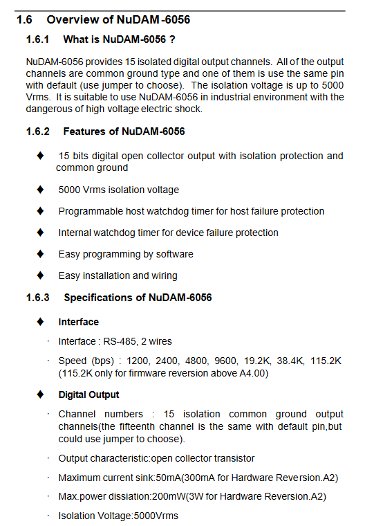
NuDAM-6056 15 channel common ground isolation open collector electrode DO 5000Vrms optoelectronic isolation, open collector output
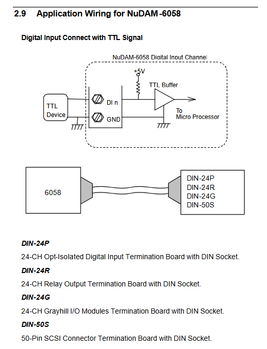
NuDAM-6058 28 channel programmable DIO; 24 analog 8255 PPI mode 0+4 fixed DI TTL levels; 50 pin SCSI connector output
NuDAM-6060 4-channel relay output (2 Form-A normally open, 2 Form-C conversion)+4-channel isolated DI relay isolation; Form-C supports normally open/normally closed
NuDAM-6063 8-way Form-A normally open relay output relay isolation
Form-A: Only NO+COM, power on/reset disconnected; Form‑C:NO / NC / COM, Power on/reset the COM-NC connection.
Relay electrical parameters: 6060 contact DC 2A@30V ;6063 DC 1A@30V .
Each model manual provides: terminal pin allocation table, internal functional block diagram; The terminal includes RS-485 DATA+/DATA -, power supply+Vs, GND, and DEFILT configuration pins.
Initialization, Software Installation, Hardware Installation and Wiring
3.1 Software Installation
Install NuDAM Administration management tool to configure module address, baud rate, and read status.
3.2 New module initialization process
Short circuit the DEFAULT pin of the module to GND and power it on to enter default mode;
Set baud rate to 9600 for RS-485 converter NuDAM-6520;
Use management software to set new address ID, baud rate, checksum switch;
Disconnect DEFAULT from GND and save the configuration.
Each module ID on the RS-485 network must be unique, and the baud rate and checksum settings must be consistent across the entire network.
3.3 Steps for connecting to an existing RS-485 network
Complete the separate initialization of the new module first;
Turn off the entire NuDAM network power supply;
Connect the RS-485 bus to the power supply, strictly pay attention to the polarity of DATA+/DATA -, and do not connect them in reverse;
Connect input and output on-site wiring;
Power on and use management software to scan all modules to confirm normal communication.
3.4 On site application wiring of various models
The manual comes with a complete wiring schematic for each model:
Digital input: TTL signal, button switch, dry contact, wet contact 24V sensor; Isolate differential input and isolate common power input;
Digital output: Open collector electrode drives SSR, LED, relay loads, requiring external current limiting resistors;
Relay output: Form A and Form C relays are connected to power loads;
NuDAM-6058 supports external DIN series terminal board (DIN-24P/DIN-24R/DIN-24G/DIN-50S) expansion.
When isolating DI/DO, attention should be paid to external isolation power supply, and the isolation ground should not be mixed with the internal ground of the module.
Complete Command Protocol Set (ASCII Command, carriage return 0x0D ends)
4.1 General Command Format
(Guidebook) (Address) (Command) [Data] [Checksum]<CR>
Address Addr: two hexadecimal digits, range 00-FF; broadcast wildcard * *;
Checksum is optional, with two additional 16 bytes added when enabled. The calculation formula is: sum all character bytes and modulo 0x100;
Return code:! Represents normal command;? Representative command error; Partial synchronization command returned with no response.
Commands are divided into three categories: general commands, functional IO commands, and special watchdog/polarity commands.
4.2 General commands (supported by all modules)
%Configuration command: Set new module address, baud rate, and enable verification; To modify the baud rate/checksum, the DEFAULT pin must be short circuited;
$Addr2: Read the current configuration of the module (address, baud rate, verification status);
$AddrM: Read the module model name;
$AddrF: Read firmware version;
$Addr5: Read the reset status and check if the module has restarted.
4.3 IO Function Commands
#**Synchronous sampling: Broadcast command, no response, all modules on the bus simultaneously latch DI sampling values, and then read them back one by one to achieve synchronous collection of multiple modules;
Addr4: Read the sampled data from the synchronous latch;
$Addr6: Instantly read DI status and simultaneously read back DO output status;
#Initial digit output command:
6050/6060/6063: Single channel writing, batch writing for all channels;
6056/6058: Supports port writing and single bit writing;
$AddrS (IOFlag): Only 6058, set 8255 PPI port direction (input/output).
4.4 Special Function Commands (All Modules)
Guide code reading and writing:~Addr0 reads the guide code; ~Addr10 modifies the command boot code (not recommended as it may cause communication issues);
Host watchdog setting~Addr2 (Flag) (Time) (SafeValue): Turn on/off the watchdog, set timeout time, and set DO safety output value in case of host failure;
~Addr3: Read watchdog configuration and security output values;
~AddrCP: Modify IO polarity (can read input high level as logic 0, software takes reverse); ~AddrCR reads polarity status;
~**Host is OK feeding dog broadcast: The host sends periodically but receives no response; When the watchdog is turned on, it timed out and did not receive this command. DO switches to a safe state.
Important precautions
Attention should be paid to the polarity of the RS-485 bus, and DATA+and DATA – cannot be interchanged; The baud rate and verification mode of all modules in the network must be unified.
The DEFAULT pin is only used for configuration and must be disconnected from GND for normal operation; Some models require modifying the JP2 jumper on the board to enable the DEFAULT function.
The host watchdog is an industrial safety function. When the upper computer crashes or communication is disconnected, the module automatically sets the output to a safe state, which is suitable for safety interlock scenarios.
Relay modules should pay attention to the rated contact power and should not be used under overload.
The checksum function is used in high interference industrial sites to reduce the probability of communication errors.