Bonfiglioli BMD series permanent magnet AC synchronous servo motor
Product Overview
BMD is a brushless sine wave permanent magnet synchronous servo motor, with a rotor made of neodymium iron boron rare earth magnets that have excellent dynamic performance, overload resistance, and are not easily demagnetized; Targeting the field of industrial automation, it is suitable for industries such as woodworking, metal processing, packaging, robotics, food and beverage, textile and leather.
There are 6 types of machine base specifications: BMD65, BMD82, BMD102, BMD118, BMD145, BMD170
Locking torque: Natural cooling 0.85-45 Nm; BMD145/BMD170 supports forced air cooling, up to 60 Nm
Power supply: three-phase 230Vac/400Vac; Insulation level F; Standard cooling IC410 naturally air-cooled; Only BMD145 and BMD170 support IC416 forced ventilation option
Protection level: standard IP65, optional IP67
Built in winding temperature sensor, supporting PTC/KTY/PT1000 three temperature measuring elements; Optional 24Vdc electromagnetic holding brake and additional inertia flywheel.
Attention: The brake only performs static holding and dynamic braking under emergency conditions; The brake and additional inertia options cannot be selected simultaneously.
Can be paired with Bangfeili AGL/AXV/ACU/ANG servo drives, and can also be matched with Bangfeili industrial gearboxes and PPG planetary reducers.
Motor body color RAL9005 black; The silver rendering of the sample is for promotional purposes only.
Bangfeili servo system architecture
Motion controller → various series of drivers → BMD/BMS servo motor → matching gearbox (industrial gearbox, PPG planetary gearbox).
Adhere to standards, nameplates, and terminology definitions
Execution standard: IEC 60034 series rotating electrical machine standard; Meets the EU Low Voltage Directive 2014/35/EU; obtained UL/cUL North American certification; RoHS 2011/65/EU; The motor body is not under the jurisdiction of the EMC directive, and only the entire drive system needs to meet EMC requirements.
Nameplate: The motor nameplate indicates the model, code, locked rotor/rated torque, voltage and current, speed, insulation level, protection, weight, installation form, number of poles, brake parameters, and serial number; The fan unit has an independent nameplate.
Parameter symbol definition: Sample definition of a complete set of electrical and mechanical symbols (locked rotor current, maximum current, back electromotive force constant Ke, torque constant KT, phase resistance inductance, thermal time constant, moment of inertia, etc.).
Working condition terminology
S1: Continuous constant load, achieving thermal balance;
S3 intermittent cycle working system, standard cycle of 10 minutes; Provide the formula for selecting and calculating the equivalent torque (M {EQU}); Provide altitude and environmental temperature derating coefficients.
Selection process of servo motor
Sample provides a complete selection process diagram:
Extract the maximum torque, corresponding speed, and maximum speed from the load cycle;
Preliminary selection of motor frame and rated speed;
Verify that all operating points fall within the motor’s maximum torque speed envelope; If not satisfied, increase the speed or choose a larger machine base;
Verify inertia matching. If the inertia does not match, activate the F1 additional inertia option, otherwise replace with a larger motor;
Calculate equivalent torque and perform derating based on environment and altitude; Verify \ (Mn × f_T × f_H>M {EQU} \); Not meeting the requirement to replace with a larger specification.
Selection of Feedback Devices
According to speed accuracy and position accuracy, it can be divided into sensorless, rotary transformer, single turn absolute value, multi turn absolute value, and functional safety absolute value encoder.
Available feedback types
SEN sensorless: estimates rotor position based on driver algorithms without the need for hardware encoders, paired with Bonfly Agile series drivers.
RES1/RES2 rotary transformer: 8kHz/10kHz excitation, anti shock vibration, single coil absolute position.
Optical encoders (Heidenhain, Sick): EnDat, Hiperface, SinCos protocols, supporting single/multi turn.
Inductive/Capacitive Absolute Value Encoder: No built-in bearings, including EnDat and Hiperface DSL models that support functional safety.
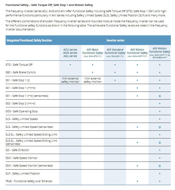
Functional safety encoder: supports safety functions such as STO, SS1, SLS, etc., and requires corresponding safety modules to be matched with the driver.
List in detail each encoder: power supply, resolution, number of turns, maximum speed, impact vibration, rotor inertia; Simultaneously provide hardware support matrices for different driver modules for each encoder.
Driver safety functions: STO, SS1, SLS, SLP, SDI, etc; Advanced sports safety features require a combination of specific driver hardware and safety encoders.
Mechanical data
Installation dimensions: comply with IEC 60072-1; B5 flange installation; The output shaft offers different diameters, with options of flat key or no key; Provide 2D engineering drawings; Each specification provides a complete set of dimensions such as flange stop, installation hole, shaft diameter, shaft length, etc; The total length of the motor will vary with the encoder, brake, additional inertia, and forced fan.
Mechanical tolerances: shaft end, key, flange tolerances comply with IEC standards; The shaft end is equipped with DIN332 axial threaded holes.
Bearing: Pre tightened grease lubricated deep groove ball bearings, lifelong lubrication; Each machine base is provided with a bearing model.
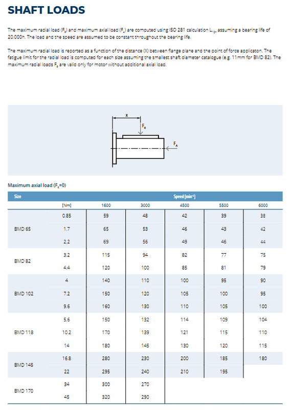
Axial load: Based on the 20000h bearing life ISO281 calculation, provide the maximum allowable radial and axial loads at different speeds, and provide the curve of radial load variation with the distance of the force application point.
Performance Parameters and Torque Speed Characteristics
Complete data sheet for each machine base (BMD65~BMD170): rated torque, power, and maximum torque corresponding to different speeds at 230V and 400V voltages; Phase resistance, phase inductance, back electromotive force constant Ke, torque constant KT, motor inertia, weight; The inertia and weight increment brought by brake options and F1 additional inertia; Separate data sheet for forced air cooling version.
Torque speed working curve
S1 continuous work area; S3 intermittent working system (20%, 50% load rate); Short term peak maximum torque \ (M {max} \).
Limiting factors: thermal limit (F insulation), mechanical speed limit, voltage limit.
BMD145, BMD170 forced air cooling IC416, significantly improving continuous output torque; The sample provides a curve chart of natural cooling and forced air cooling for all machine bases at 230V/400V.
All optional configurations (Options)
7.1 Thermal protection
PTC thermistor; KTY84‑130; PT1000 (TC1) platinum resistor.
7.2 F24 24V DC Electromagnetic Holding Brake
Only used for static maintenance, dynamic braking is prohibited (except for emergency power outage); After installation, the length and weight of the motor increase; The brake power cord is integrated into the power connector.
The table provides the rated torque, current, power, suction/release time, and inertia weight increment for each specification of brake.
Cannot be selected simultaneously with F1 additional inertia.
7.3 F1 additional flywheel inertia
Enhance the inertia of the motor rotor and improve the inertia matching of high inertia loads; Motor length and weight increase; Each machine base provides inertia increment and mass increment.
7.4 V1R/V1S/V2R/V2S forced ventilation unit (limited to BMD145, BMD170 only)
IC416 forced air cooling enhances continuous torque; Fan IP54; The whole machine can be pre installed at the factory, or it can be used as a retrofit kit for later installation; The modification kit requires modifying the motor housing opening; Provide a complete set of kit ordering codes and electrical parameters.
7.5 Connector scheme
Divided into power connectors, signal encoder connectors, and hybrid integrated connectors (power+encoder).
Corner rotatable socket (P1-S1); Straight socket (P3-S3); 1-meter loose wire (P2-S2, with terminals or D-SUB connectors);
H-series hybrid connector: used for Hiperface DSL (ENB9-ENB12) and some EnDat encoders, with a single cable transmitting both power and encoder signals simultaneously.
The sample provides complete pin definitions and line color comparison tables for each type of connector, distinguishing pin layouts with/without brakes, sensors without encoders, and various encoders.
servo matching cables Servocables
Divided into power cables (orange), signal cables (green), and hybrid cables (orange).
Power cable: transmit motor power+brake; Divide the cross-sectional area of different conductors; Optional 3/5/10 meters; Drag chain application, oil resistant shielding, DESINA standard; The fan unit cable is gray.
Signal cable: specifically designed for encoder signals and thermal protection.
Hybrid cable: simultaneously transmitting power, brake, and encoder signals.
Sample: Cable mechanical and electrical parameters, ordering coding rules; Motor cable matching selection table; Connector model and crimping range; Cable dimensions.