Bonfiglioli EVOX platform CP coaxial helical gear reduction motor
General Fundamentals and Environmental Constraints
1.1 Environmental working conditions
temperature
Gearbox: Standard environment -25 ℃~+50 ℃; Contact technology is required for temperatures below -25 ℃ or above+50 ℃; Start with partial load at -25~-10 ℃ to avoid gear damage from cold start impact.
EVOX motor standard operating temperature -15 ℃~+40 ℃; Power derating at temperatures above 40 ℃: 97% at 45 ℃, 94% at 50 ℃, 90% at 55 ℃, and 86% at 60 ℃.
elevation
Reference condition altitude<1000m; output power derating for altitude>1000m;
If the altitude change is greater than 1000m, and the factory pre fills the oil, it is necessary to open the oil drain plug to balance the pressure inside and outside the housing to prevent oil leakage caused by abnormal internal pressure.
Noise and vibration: The noise test of the gearbox is based on UNI ISO 3746; The motor complies with CEI EN 60034-9; The noise of the gearbox is usually lower than that of the matching motor.
Storage requirements
Prohibit outdoor storage in damp conditions, and elevate equipment off the ground;
Apply rust inhibitor to the processing surface (flange, shaft extension); Long term storage requires oil injection and replacement of ventilation plugs with closed plugs; Restart and add the correct grade of lubricating oil.
Efficiency: Coaxial helical gears have an efficiency of approximately 0.98 per stage, with 2nd stage ≈ 0.96 and 3rd stage ≈ 0.94.
1.2 Complete selection input parameter table
Before selection, a complete set of operating conditions must be collected for calculation and verification. Key parameters include output power (P_ {r2}), output torque (M {r2}), and input/output speed (n1/n2); Input/output shaft radial load \ (R_ {c1}/R_ {c2} \), load action distance \ (x_1/x_2 \); Axial load \ (A_ {c1}/A_ {c2} \); Load inertia \ (J-c \); Environmental temperature and altitude; Work schedule S1-S9; Hourly startup frequency \ (Z_r \); Motor voltage, brake torque, protection level, insulation level.
1.3 Service Factor Calculation
The service coefficient depends on three factors: load shock level K, number of starts per hour (Z_r), and daily operating hours
K1 uniform load \ (K \ le0.25 \);
K2 moderate impact (0.25<K \ le3 \);
K3 strong impact (3<K \ le10 \);
K>10, It is necessary to contact the manufacturer for evaluation and not directly apply charts.
Calculate the torque \ (M2=M2 × SF \), select the gearbox to ensure the rated output torque \ (M2 \ ge M2 \).
Work system correction: S2 short-term and S3 intermittent cycle work system, with a default cycle of 10 minutes, using \ (f_m \) power amplification factor.
1.4 Selection verification items
Mechanical capacity verification;
Thermal capacity verification: When the altitude is less than 3000m and the environment is less than 50 ℃, thermal power generally does not become a bottleneck; Beyond this range, thermal verification must be conducted;
External load verification of the shaft (radial load, axial load).
1.5 Radial Load Calculation Formula and Position Correction
\(R {c}=\ frac {2000 \ cdot M {a} \ cdot K {r} {d} \) Sample allowable radial load reference condition: the load application point is at the midpoint of the axis extension. The load is offset towards the axis end, requiring geometric conversion \ (R_a=R_ {max} \ frac {l1} {l2+x} \), and the converted \ (R_a \) must be greater than the actual calculated load \ (R_c \).
Simultaneously bearing radial and axial composite loads, it is necessary to submit a Bangfeili technical evaluation.
EVOX-CP Coaxial Gear Unit Product Overview
2.1 CP reducer series specifications
CP coaxial helical gear, machine base: CP07, CP17, CP37, CP47 (CP57, CP67 will be launched later)
Rated output torque of machine base, reduction ratio range, maximum radial load output (standard bearing)
CP07 55 Nm 2.8‑81.2 1470 N
CP17 100 Nm 2.4‑85.9 2460 N
CP37 200 Nm 2.3‑133 4110 N
CP47 335 Nm 2.4‑172 5240 N
Reduction stages: 2nd and 3rd helical gear transmission.
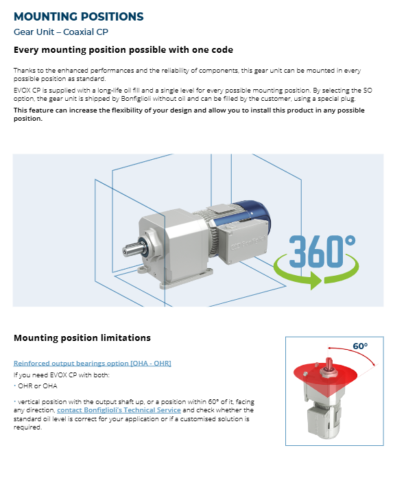
Highlight: Single oil level design, with the same product code supporting 360 ° installation posture for all installations; No need to change the order code based on the installation location.
Exception: When using OHR/OHA reinforced output bearings with the output shaft facing upwards and within a range of 60 °, it is necessary to contact the technical team to confirm the oil level compatibility.
2.2 Shell version
P: Foot installation; F: Flange output; U: Universal box without base; PF: Foot+flange composite version.
Input interface:
IEC motor adapter;
NEMA North American motor adapter;
HS/NHS solid input shaft (metric/imperial).
2.3 Model coding rules
CP 37 2 N P F140 7.5 S20 All+Options+Motor
CP: Series; 37 machine base; 2 levels; N: British output shaft (M is metric); P base; F140 output flange; 7.5 speed ratio; S20 input adapter; All represents all installation postures; Add various option codes later, and finally specify the matching motor model.
2.4 Factory lubrication
Standard factory filled PAG synthetic long-acting oil for lifelong lubrication;
Oil volume of each machine base: CP07=0.35L; CP17=0.7L; CP37=1.1L; CP47=1.8L。
Rich lubricant options: PAO synthetic oil, mineral oil, NSF H1 food grade oil; The SO option represents not adding oil at the factory, but adding it on-site by the customer.
It is strictly prohibited to mix mineral oil with synthetic oil; Mineral oil is recommended to be used only under service factor S ≥ 1.3 conditions.
Detailed explanation of all CP gearbox options
Function Description of Option Code
SO factory does not inject oil, lubricating oil is added on site
All PV inputs and outputs are Viton fluororubber oil seals, suitable for high and low temperature working conditions
PN All NBR Nitrile Rubber Oil Seals
DL output dual lip oil seal, dustproof and waterproof
AR/AL unidirectional backstop, only supports HS/NHS solid input shafts; AR right-hand freedom, AL left-hand freedom
RB2 low back gap version; Standard backlash level 2 is 11-18 arcminutes, level 3 is 20-25 arcminutes; RB2 low back clearance 2nd level 7-12, 3rd level 10-16 angular minutes
IHB input reinforced bearing, suitable for solid input shaft, enhances input radial load
OHR1 output strengthens radial bearings, significantly increasing allowable radial loads (preferred for belt and chain drives)
OHA1 output strengthens axial bearings, suitable for screw conveyors and axial pumps
EX ATEX explosion-proof 2G/2D, T4 temperature rating (135 ℃), suitable for Zone 1 gas and Zone 21 dust; The EX version has a large number of mutually exclusive options and cannot use NEMA, imperial shafts, backstops, stainless steel FO, C3/C4 anti-corrosion, etc
FO stainless steel output shaft, screws, nameplates, etc., in humid and corrosive conditions
C3/C4 anti-corrosion coating, compatible with ISO 12944-2; C5M requires separate consultation
RALxxxx custom paint color
AC/CC product compliance certificate, factory inspection certificate
ATEX-EX explosion-proof version comes with: fluororubber seal, oil level check plug, factory filled synthetic oil, temperature indicator label; I class mining equipment in 0/20 zone is not supported.
Performance, axle load, external dimensions
Performance table: Provide the rated output torque (M2), output speed (n2), and maximum input power corresponding to each speed ratio at input speeds of 1400 rpm and 1700 rpm, respectively; At the same time, the table indicates whether the IEC/NEMA/solid axis adapter is geometrically compatible; Highlight when the service coefficient S is less than 0.9, indicating that the motor power cannot exceed the maximum input power in the table.
Axle load table: distinguish between standard bearings and OHR/OHA reinforced bearings; Distinguish the maximum radial load for different output speed ranges; The axial load value is only applicable to the direction of axial force towards the reducer body; The outward axial thrust or radial axial composite load must be related to technology.
Drawing size set:
P foot, F flange, U universal box, PF composite version 2D engineering dimensions;
IEC, NEMA input flange size; HS/NHS solid input shaft size;
Metric and British output shaft dimensions;
The total length and flange dimensions of the complete set of deceleration motors.
EVOX BXN/MXN/MNN asynchronous motor module
EVOX motors are divided into three sub series:
MNN: IE1 Standard Efficiency (NEMA Standard) Compact Motor
MXN: IE3 Ultra High Efficiency (NEMA Premium) Compact Motor, Compact Docking with CP Reducer
BXN: Standard IEC base IE3 high-efficiency motor, standard B5/B3 flange
5.1 Power Base Coverage
Compact MXN/MNN: 05MA (0.12kW)~35M (4kW); Standard BXN: 63MA~132M, power 0.12~7.5 kW; 4-pole motor is the main motor.
5.2 Basic specifications of motor
Standard cooling IC411 self fan cooling; F-class insulation; Protection IP55; Rotor half key dynamic balance N-level vibration level.
9-terminal design of junction box, supporting global adaptation to multiple voltages; The junction box is rotatable; There are multiple specifications for cable glands.
Bearing: Lifetime pre lubricated deep groove ball bearings, table of DE/NDE bearing models for different machine bases.
Compliance certification: CE, UKCA, EAC, UL/cUL, INMETRO Brazil, BIS India, CCC China, GEMS energy efficiency in Australia; Meets LVD, EMC, RoHS, and ErP energy efficiency directives.
Rich motor options: FD direct loss electric brake (with manual release R/RM), thermal protection PTC/KTY, encoder, second shaft extension, independent forced air cooling, anti condensation heater, etc.
5.3 Motor reducer combination
Two assembly forms:
Compact: MXN/MNN directly interfaces with CP flange, resulting in a shorter overall length;
IEC Adapter: BXN standard IEC motors are assembled to CP reducers through adapters.
Product Application and Bangfeili EVOX Platform Ecology
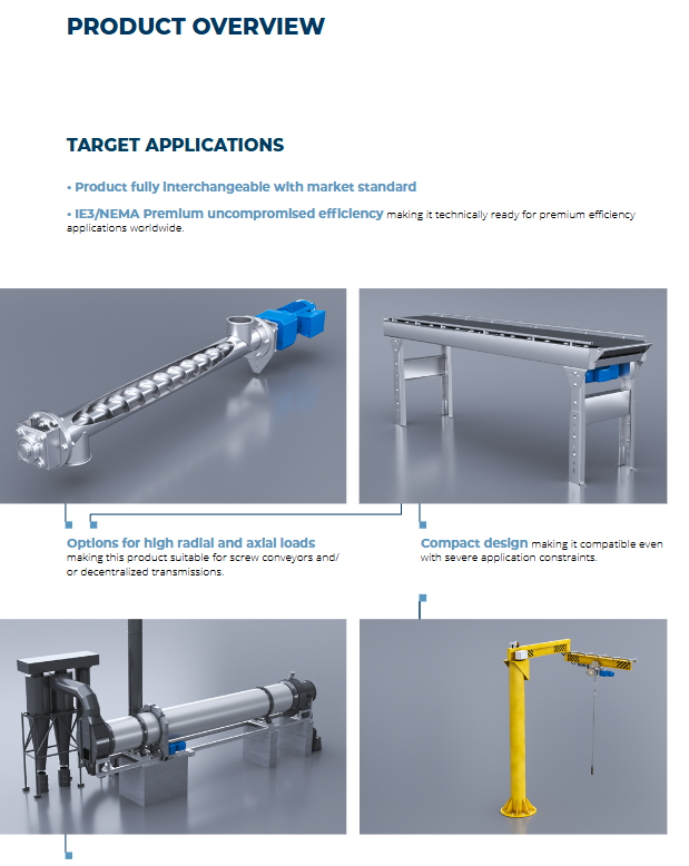
Target applications: Packaging machinery, material conveying, fan HVAC, woodworking, textile, general industrial assembly line; Can be equipped with the full range of Bangfeili drives (Agile, Active Cube, ANG, AxiaVert, distributed DGM inverters) to achieve a complete drive solution.
Development history of the platform: self-developed motors in the 1990s; 2001 Acquired Vectron to enter the inverter industry; Developed BMD servo in 2012; 2017 Reluctance BSR Motor; Complete EVOX asynchronous motor platform iteration in 2020.