Bonfiglioli RAN series bevel gear angle reducer
Basic definition and selection calculation
1. Core parameters of torque and power
Rated output torque Mn2 (Nm): Service factor \ (fs=1 \), capable of transmitting output torque under continuous and uniform load, related to input speed n1.
Required torque Mr2 (Nm): the output torque required by the actual operating conditions of the equipment\ (M_{r2} \le M_{n2}\)。
Calculation torque Mc2 (Nm): Calculation torque for selection \ (M {c2}=M {r2} \ times f_s \) Selection criteria: \ (\ boldsymbol {M {n2} \ ge M {c2} \)
Rated input power Pn1 (kW): Given in the sample table\ Under the condition of fs=1, input power is allowed.
2. Service coefficient \ (f_s \)
Service coefficient comprehensive: daily operating hours h/d, hourly start stop frequency \ (Z_r \), load impact level K1/K2/K3.
Mass acceleration coefficient \ (\ boldsymbol {K=Jc/Jm} \), \ (Jc \) load inertia\ Motor inertia
K1 uniform load: \ (K \ le0.25 \)
K2 moderate impact: (0.25<K \ le3 \)
K3 Strong Impact: (3<K \ le10 \)
\(\ boldsymbol {K>10} \), direct table lookup is prohibited and must be evaluated by contacting the technical department of Bonfly.
Key reminder: In high-risk lifting conditions, gearbox failure can cause personal injury. Regardless of the fs value obtained from the table, it is recommended to consult technical support in advance.
3. Complete selection steps
Determine the service factor \ (f_s \) based on the load level K, start stop frequency, and daily operating duration;
Calculate \ (M {c2}=M {r2} \ times f_s \);
Determine the transmission ratio \ (i=n1/n2 \) based on the input and output speeds, and RAN only has i=1 and i=2;
Select the machine base that meets the requirements of \ (M2} \ ge M2} \) in the performance table corresponding to the input speed (1400/900/500rpm);
If equipped with IEC motors, check the geometric compatibility of the motor adapter.
4. Three mandatory checks after selection
Peak instantaneous torque: The maximum instantaneous load shall not exceed 200% Mn2, and a torque limiter shall be configured when exceeding the limit.
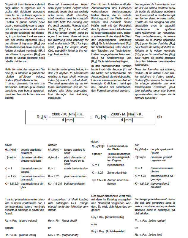
Radial cantilever load: The actual radial load of the input and output shafts must be less than the allowable radial load Rn1/Rn2 of the sample.
Axial thrust load: verify the allowable axial load; Radial+axial composite heavy load condition, contact the manufacturer for evaluation.
Maintenance requirements
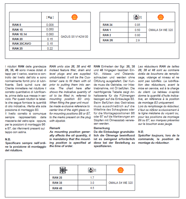
Lifetime lubrication version: Pre filled with lubricating grease/synthetic oil at the factory, no need for regular oil changes under normal non polluting conditions.
Non lifetime lubrication models: Perform the first oil change after approximately 300 hours of operation, while thoroughly flushing the interior of the casing; Mineral oil is strictly prohibited from mixing with synthetic oil.
Reference Table for Oil Change Cycle
Oil Temperature Mineral Oil Synthetic Oil
<65℃ 8000h 25000h
65‑80℃ 4000h 15000h
80‑95℃ 2000h 12500h
Tip: RAN small specification 8-25 is maintenance free for life with lubricating grease, and there are no oil drain or oil injection plugs; RAN1/2/2R with oil level sight glass; RAN28-38-48 does not come with oil at the factory and needs to be refilled on site.
Installation specifications
The reducer base must be firmly fixed to eliminate vibration; It is recommended to configure hydraulic couplings and torque limiters for impact and locked rotor conditions.
Protect the shaft extension and oil seal before painting, as paint can corrode the rubber oil seal and cause oil leakage and failure.
The coupling and pulley assembled on the output shaft must have an internal hole tolerance of ISO H7; Disassemble and use the threaded hole on the shaft end to match the puller, and do not strike it.
Clean the assembly contact surface thoroughly, provide rust prevention protection, and prevent biting and biting.
The entire equipment needs to comply with the EU Machinery Directive 2006/42/CE.
Confirm that the oil level matches the installation posture specified in the order before commissioning.
For outdoor installation, protective covers must be added to avoid rain and direct sunlight.
Storage conditions
Prohibit storage in open or humid environments; Elevate the equipment and prohibit direct contact with the ground.
Apply rust inhibitor (Mobilarma 248 or equivalent) to the machined surfaces of flanges, shaft extensions, etc.
Long term storage: Place the vent plug in the highest position and fill the box with lubricating oil; Return to operation and restore the specified oil level and product.
Supply conditions
Pre assemble according to the installation posture specified in the order at the factory;
Complete factory factory factory testing;
Cooperate with the processing surface without painting;
The IEC adapter version provides motor installation bolts and nuts;
The shaft extension is equipped with a plastic protective cap;
The large machine base is equipped with lifting lugs.
Product ordering code, version, and options
1. Example of ordering code
RAN 28 S A 1 090 B5 B3
RAN: series; 28 machine base; S output shaft form (S single shaft/D double extension shaft); A structural form; I Speed ratio; 090 motor flange specifications; B5 motor flange; B3 installation posture
Input options: HS=solid input shaft;
Installation posture: B3 (default) B6、B7、B8、V5、V6。
Optional Accessories
LO: RAN28/38/48 models, pre filled with lubricating oil at the factory (this series defaults to no oil at the factory).
PV: Viton fluororubber oil seal, used for high-temperature environmental conditions.
Structure execution versions A/B/C/D/E/F
Different versions are available for different machine bases:
RAN8‑15:A/B;
RAN18.14/20/20CAVO/25:A/B/S;
RAN24/28/38/48:A/B/C/D/E/F;
RAN1/2/2R special heavy-duty axial thrust model.
Lubrication system
Differentiation of lubricating media for machine base
Lubricating grease (lifetime): RAN8, 15, 18.14, 20, 20CAVO, 25 → GADUS S5 V142W 00 lubricating grease; No oil plug.
Synthetic oil lifelong oil bath: RAN24, RAN1, RAN2, RAN2R → OMALA S4 WE320 synthetic oil; RAN1-2-2R is equipped with an oil level sight glass.
On site lubricating oil injection: RAN28-38-48, no oil from the factory, user on-site injection of OMALA S4 WE320.
Environmental temperature boundary
Allowable ambient temperature: -20 ℃~+40 ℃
Environment -20 ℃~-10 ℃: It is forbidden to start directly with load. It is necessary to preheat without load, and the box temperature should be ≥ -10 ℃ before loading.
Important: The installation posture directly determines the fuel quantity, and the installation position B3/B6/B7/V5/V6 must be clearly specified when ordering.
Axial load calculation
1. Calculation formula for radial cantilever load
\(R_{c1}[N]=\frac{2000 × M_{1}[Nm] × K_r}{d[mm]} \quad ; \quad R_{c2}[N]=\frac{2000 × M_{2}[Nm] × K_r}{d[mm]}\)
\(M1/M2): Transmission of torque on the shaft; D Transmission component pitch diameter;
Kr coefficient: Chain Kr=1; Gear Kr=1.25; Belt drive Kr=1.5-2.0;
Verification: \ (R_ {c1} \ le R_ {n1} \), \ (R_ {c2} \ le R_ {n2} \).
2. Axial thrust load
Simultaneously existing rated radial load conditions: \ (A_ {n1}=0.2 × R_ {n1} \ quad; \quad A_{n2}=0.2×R_{n2}\)
No radial load, pure axial thrust, allowable axial load can be increased to 0.5 × Rn.
RAN1/RAN2/RAN2R special models: specifically designed for extremely high axial thrust (screw lift mechanism); Allowable axial force at input speed \ (n_1 \ le100 \ mathrm {rpm} \):
RAN1:50000 N
RAN2:80000 N
RAN2R:150000 N
If the input speed is greater than 100rpm and the axial load decreases, technical consultation is necessary.
Performance parameter table
The sample provides three sets of input speed performance: 1400 rpm, 900 rpm, and 500 rpm; Each machine base is given: transmission ratio i, output speed n2, rated output torque Mn2, rated input power Pn1, allowable radial input shaft Rn1, and allowable radial output shaft Rn2. Machine base specifications: RAN8, 15, 18.14, 20, 20CAVO, 25, 24, 28, 38, 48, as well as heavy-duty axial RAN1, RAN2, RAN2R.
The RAN1-2-2R performance table is limited to the condition of n1 ≤ 100rpm.
Motor adapter and external dimensions
Motor adapter: The table lists the IEC motor flange specifications that can be matched with each RAN base; The combination of the [] symbol needs to be confirmed with technical personnel for feasibility and cannot be directly selected.
Outline drawings: Provide all two-dimensional engineering drawings of the machine base; Mark all key dimensions: shaft diameter, keyway, flange, center distance, mounting hole, stopper, etc., according to metric DIN standards.