Bonfiglioli CM-CAN CANopen communication module
Hardware installation
Mechanical installation: Remove the cover plate of the frequency converter when the power is turned off; Install PE grounding spring M4 screw; Insert CM-CAN into Slot-B slot, and tighten M2 screw to PE spring plate; Knock open the prefabricated opening on the cover plate to lead out the X310 DB9 connector, and restore the cover plate.
X310 DB9 interface pin (ISO 11898-2 high-speed CAN)
|Pin | Signal | Description|
|Shell | Shielding | Connected to PE|
|1,2 | CAN-L | Parallel connection|
|7,8 | CAN-H | Parallel|
|3,6 | CAN-GND | Ground|
|9 |+5V output|
|4,5 | NC | Vacant|
Terminal resistance dip code S1: Bus physical head and tail nodes S1=ON; All in the middle are turned off, and it is prohibited to use both onboard dialing and external plug terminals simultaneously.
Cable: CAN Bus dedicated twisted pair braided shielded cable, with PE extensively connected at both ends of the shielding layer; power cable and communication cable are physically separated for wiring.
Basic bus parameters
Parameter 385 CAN Baud rate baud rate, the baud rate of all nodes on the entire bus must be consistent
|Settings | Baud Rate | Maximum Bus Length|
|1 |10kBaud |5000m |
|2 |20kBaud |2500m |
|3 |50kBaud |1000m |
|4 |100kBaud |500m |
|5 |125kBaud |500m |
|6 | 250kBaud | 250m (factory default)|
|7 |500kBaud |100m | |8 |1000kBaud |25m |
Parameter 387 CAN Node Number Node Address
0: CANopen interface disabled (factory default);
1-127: Slave node number; After modifying the parameters, the frequency converter will automatically reset and take effect; The CANopen bus supports a maximum of 127 nodes.
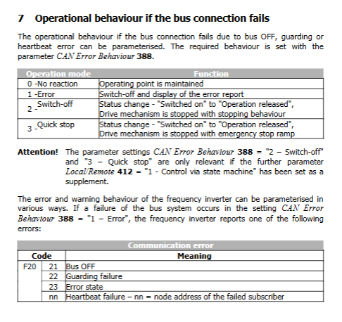
Parameter 388 CAN Error Behavior Bus Fault Behavior (DS402 Object 0x6007/0) | Value | Mode | Function | | ——- | ——– | | 0 | No reaction | Maintain current operating point, no action | | 1 | Error | Report fault, frequency converter shutdown | | | 2 | Switch off | State switch to “closed”, execute fast stop ramp shutdown | | | 3 | Quick stop ||
Prerequisite for Mode 2/3 to take effect: 412=1 state machine bus control mode.
Bus fault code:
F20-21: CAN Bus OFF bus is turned off
F20-22: Guarding failed
F20-23: Error State Error Status
F23-nn: Heartbeat failed, nn=Fault Node ID
CANopen Object Dictionary
The object dictionary is divided into four categories: communication object 0x1nn, general object 0x6nn, device control object 0x60xx, speed mode object 0x604x, and vendor defined object 0x2000/0x2nnn.
4.1 Communication Object 0x1nn (DS301)
0x1000 Device Type: Device configured as DS402 driver (0x00001615)
0x1001 Error Register (8-bit encoding): General errors, current, voltage, temperature, communication faults, etc.
0x1008-0x100A: Manufacturer’s device name, hardware version, software version (read-only string).
0x1014 Emergency ID Emergency message COB-ID; Default 128+NodeID.
0x1016 Consumer Heartbeat Time: Monitor the heartbeat timeout of up to 3 external nodes.
0x1017 Producer Heartbeat Time: This machine sends heartbeat cycles externally, 0=turned off.
0x1018 Identity object: Vendor ID=0x000000D5.
Emergency message format: 8 bytes, standard CiA emergency code+Bangfeili internal fault code.
4.2 PDO Process Data Objects (2 RxPDO, 2 TxPDO)
The transmission type is fixed at 255 (event triggered) and does not support SYNC synchronization mode.
|PDO | COB-ID Default | Default Mapping Content |
| RxPDO1 (receive 1) | 512+NodeID | 0x6040 Control Word |
| RxPDO2 (receive 2) | 768+NodeID | 0x6040 Control Word+0x6042 Target RPM |
| TxPDO1 (send 1) | 384+NodeID | 0x6041 Status Word (event triggered, status change sent) |
| TxPDO2 (send 2) | 640+NodeID | 0x6041 Status Word+0x6044 Actual RPM; Support inhibition time of 50ms and event time of 1000ms|
PDO can be disabled by setting COB-ID maximum bit=1;
Speed unit: RPM, completed by polar object 0x604D ↔ Internal Hz frequency conversion.
4.3 SDO Service Data Object
Server‑SDO:0x1200; Rx‑SDO ID =1536+NodeID; Tx‑SDO ID=1408+NodeID; Support expedited fast transmission.
Two ways to access frequency converter parameters
Manufacturer object 0x2nnn (recommended)
Index=0x2000+frequency converter parameter number; Subindex=dataset number;
Dataset 0-4: Write to EEPROM; Dataset 5-9 only has RAM (lost during power outage, used for periodic writing, protecting EEPROM, EEPROM has a lifespan of approximately 1 million erasures).
Decimal parameter: Amplify integer transmission, for example, transmit 1050 at 10.5Hz.
Manufacturer composite object 0x2000 (alternative): Subindex 01=int/uunt; 02=long; 03=string, The message is more complicated.
SDO Abort abort error code, standard CiA DS301 error code, corresponding to parameters not present, read-only, non writable, dataset error, etc.
4.4 DS402 Drive Control Object
0x6060/0x6061 Operation mode: This module only supports speed mode=2, other modes are ignored.
0x6040 Control Word control word; 0x6041 Status Word, strictly following the DS402 DRIVE COM state machine.
0x604D Pole number motor pole number (not pole pairs, pole pairs multiplied by 2), used for converting RPM to Hz.
0x6042 Target velocity RPM; 0x6044 Control effort actual speed (RPM read-only).
0x6046 minimum/maximum speed; 0x6048 Acceleration (Δ speed/Δ time); 0x6049 decelerates.
Three CANopen control modes
Hardware terminal S1IND has the highest hardware enable priority! Bus cannot replace hardware security enablement.
Mode 0: Control via contacts (terminal control, 412=0)
All start stop commands come from the DI terminal; CANopen control word is invalid; Only the status word provides feedback on the driver’s status. State machine simplification: ready/running enabled/faulty.
Mode 1: Control via state machine (DRIVECOM complete state machine, 412=1, standard CANopen control)
Complete DS402 state machine: power-off initialization → closing prohibition → ready closing → operation enable → quick stop → fault.
Control word bit0-bit7 execution status jump: Switch on, Quick Stop, Operation enable, Fault Reset fault reset;
Parameter 392 State transition5: Switching back to ready shutdown behavior from operation enable: 0 free coasting, 1 DC braking (V/F only), 2 ramp shutdown factory default;
Quick Stop logic: Execute a fast stop ramp, maintain DC braking after reaching zero speed, and cut off output after reaching the holding time.
After the fault occurs, there is an internal 15 second shielding time, and the fault reset command must wait for this time.
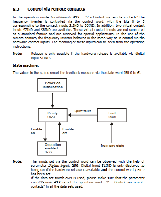
Mode 2: Control via remote contacts virtual terminal mode (412=2)
The control word maps hardware digital inputs S1IND~S6IND per bit, and the bus virtual DI; hardware S1IND still needs to be enabled by hardware; The behavior of the driver is completely equivalent to hardware terminal wiring.
Given source logic
1=Only internally given; 2=Given only the target speed on the CAN bus; 3=Internal+bus given superposition; Can monitor actual value parameters:
228: Internal reference frequency (Hz)
282: CAN bus reference frequency (Hz)
283: Slope output total reference frequency (Hz)
Malfunctions and warnings
Warning word 270 is a 16 bit encoding, Bit13=Sysbus system bus warning;
CANopen exclusive fault F20-xx, F23-xx heartbeat fault; Emergency message reports a fault.