Bonfiglioli C series inline helical gear explosion-proof reducer
General Information
1.1 Symbols and Units of Measurement
Define the parameters used for all selection calculations:
Symbol meaning
\(f_s \) coefficient used to characterize the severity of load conditions
\(f_ {TP} \) temperature correction coefficient, this series of helical gear reducers \ (f_ {TP}=1 \), only the worm gear reducer needs to be corrected
I reduction ratio \ (i=n1/n2 \), input speed/output speed
\Rated torque of output shaft (sample value of f_s=1)
\(M2} \) The device actually needs to output torque\ (M2=M2 · Fs) Calculate torque
\(R_n \) allows radial load\ (A_n \) Allowable axial thrust load
\(K=J-c/Jm \) Load acceleration coefficient, load inertia/motor inertia, used to distinguish between K1 uniform, K2 moderate impact, and K3 strong impact loads
\(Z_r \) number of startups per hour; I work interval rate\ (\ eta-d \) Dynamic efficiency
Axial load rule: When simultaneously subjected to rated radial load, axial load \ (A_n=0.2 · Rn \) is allowed; When there is no radial load, the axial load is allowed to reach 0.5 · Rn.
1.2 Introduction to ATEX Explosion proof Directive
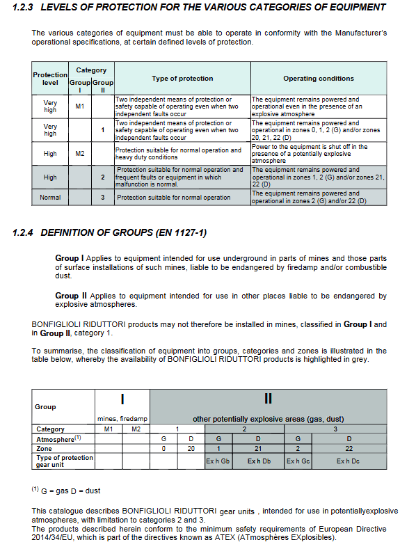
Definition of explosive environment: a mixture of combustible gases, vapors, mists, or dust mixed with air under atmospheric conditions and ignited to spread flames; The potential explosive environment refers to the working conditions that may become explosive environments.
Classification of Hazardous Areas
Gas environment: Zone 0 (continuous), Zone 1 (occasionally occurring normally), Zone 2 (rarely short-term)
Dust environment: Zone 20 (continuous), Zone 21 (normal occasional), Zone 22 (rarely short-term)
This product is suitable for: Zone 1/2 (gas), Zone 21/22 (dust); It does not support zones 0 and 20 and cannot be used for Class I underground mining equipment. The corresponding protection types are Ex h Gb, Ex h Db, Ex h Gc, and Ex h Dc.
Directive priority: ATEX 2014/34/EU has a higher priority than Machinery Directive 2006/42/EC; it officially came into effect on April 20, 2016, and not only electrical equipment, but also mechanical, hydraulic, and pneumatic equipment are subject to control.
Declaration of conformity: The validity of the product conformity certificate must strictly comply with the user manual for installation and use. The manual can be downloaded from the official website.
1.3 Use, Installation, and Maintenance
Multi language PDF download of user, installation, and maintenance manuals from the official website, kept near the equipment site for reference by operators; The manufacturer reserves the right to revise the manual.
1.4 Equipment selection
1) Selection steps
Determine the usage factor \ (f_s \): Obtain it by referring to the sample curve chart based on the load type K1/K2/K3, hourly startup frequency \ (Z_r \), and daily operating hours.
Calculate the required motor shaft power \ (P_ {r1}=\ frac {M {r2} · n2} {9550 · \ eta-d} \).
2) Two types of gearbox selection methods
① Equipped with IEC motor interface reducer (with standard motor)
Requirement: \ (P_ {n1} ≥ P_ {r1} × f_s \); Motor power \ (P_1 ≥ P_ {r1} \); Safety factor \ (S=P_ {n1}/P_1 ≥ f_s \)
Exception: C122, C222, C322, speed ratio i>40, starting more than 30 times per hour, use factor multiplied by 1.2 for verification.
② Solid input shaft reducer (HS input, user provided drive)
Calculate the torque (M2=M2 × Fs × Tp) and select the model with rated output torque (M2 ≥ M2).
3) After selection, the project must be reviewed
Instantaneous peak torque: The allowable peak torque is about 200% of the rated torque, and it is necessary to configure a torque limiter;
Radial load: Actual radial load ≤ sample allowable radial load \ (R_n \);
The axial thrust load shall not exceed the allowable value of the sample.
4) ATEX explosion-proof version reducer operating hard conditions
Environmental temperature: -20 ℃~+40 ℃;
The installation position shall strictly follow the order nameplate, and changing the installation position requires written approval from Bonfly; Prohibit arbitrary tilting installation;
The maximum speed of the supporting motor shall not exceed 1500 r/min; The motor driven by the frequency converter must be adapted to the frequency converter itself, and it is not allowed to exceed the upper limit of 1500r/min;
All installation and maintenance manual terms must be followed.
C-series potential explosive environment inline helical gear reducer
2.1 Structural characteristics of ATEX explosion-proof version
Oil level inspection and maintenance plug; Pre filled with long-life synthetic lubricating oil corresponding to the installation position at the factory;
Standard fluororubber sealing ring; The output shaft adopts double sealing rings; No plastic components;
The nameplate indicates the equipment category and explosion-proof protection type.
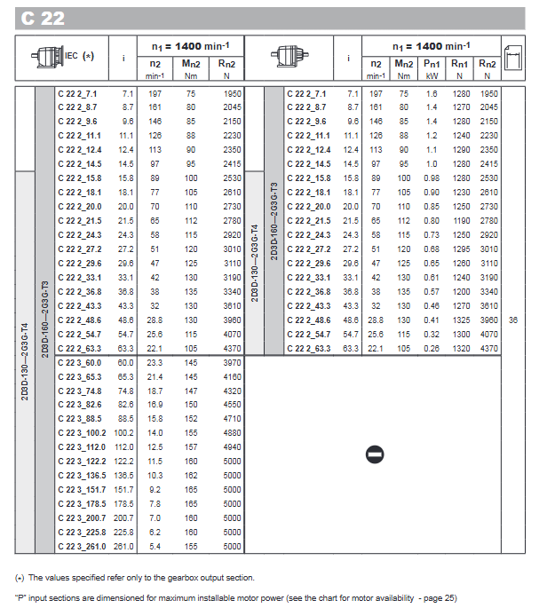
Model framework: C12, C22, C32, C36, C41, C51, C61, with a rated output torque of 56-1600Nm.
2.2 Structure Version
P: Foot installation; F: Flange installation; U: UNIBOX universal box body; UF: UNIBOX with assembly flange.
2.3 Ordering Code
Encoding example: C 51 2 P 51.4 HS B3 2D3D-130
C=inline helical gear; 51=machine base; 2=2-level deceleration; P=installation form; 51.4=reduction ratio;
HS=solid input shaft; B3=installation location; At the end is the explosion-proof option:
Table
Explosion proof options are applicable to surface temperature limits in the designated area
2D3D-130 Dust 21/22 Zone Surface ≤ 130 ℃
2D3D-160 dust 21/22 zone surface ≤ 160 ℃
2G3G-T3 gas 1/2 zone temperature level T3 maximum 200 ℃
2G3G-T4 gas 1/2 zone temperature level T4 maximum 135 ℃
2.4 Installation position
P-foot models: B3, B6, B7, B8, VA, VB;
F/UF flange models: B5, B51, B53, B52, V1, V3.
2.5 Lubrication
Add long-lasting synthetic oil that is compatible with the ordered installation position at the factory; The screw plug is sealed during transportation, and the ventilation screw plug must be replaced before on-site operation; C12/C22/C32 no overflow oil level plug, oil level check reference manual. Refer to the maintenance manual for the position of the oil level plug and the amount of fuel added.
2.6 Allowable cantilever load
Radial load: Provide calculation formula, the load action position is offset from the axis centerline, and position coefficient correction is required; Provide a/b/c parameter table for each machine base; The calculation of radial load must meet the requirement of ≤ allowable radial load.
Thrust axial load: \ (An_1=0.2 · Rn1 \), \ (An_2=0.2 · Rn2 \); When the axial load is too large, the manufacturer needs to evaluate it.
2.7 Performance parameter table of reducer
The sample provides the performance of all machine bases (C12~C61): reduction ratio i, output speed \ (n2 \), rated output torque \ (M2} \), input rated power \ (P1} \), input/output allowable radial load Rn1, Rn2, and label the explosion-proof optional configuration corresponding to each speed ratio. Input reference speed n1=1400r/min.
2.8 Motor adaptability
Geometric compatibility table: List the IEC motor frame numbers P63-P180 that can be adapted to each frame;
Maximum installable power: Geometric compatibility does not equal power compatibility. The table provides the maximum allowable motor power for each speed ratio, and the selection must be checked simultaneously.
2.9 Rotational inertia
Provide the moment of inertia of the high-speed side (input shaft) in units of 10 for each model and speed ratio^ {-4}kg ·M ^ 2 \), distinguish different IEC motor flange specifications, used for starting and stopping power school nuclear.
2.10 Overall dimensions
Provide engineering drawings for all installation forms of P/F/U/UF models, including complete dimension tables for output shaft, input shaft dimensions, flanges, feet, total length, bolt specifications, etc., covering C12 to C61; Distinguish between IEC motor input version and HS solid shaft version.