Foxboro E69F-BI2 on-site installation type electric pneumatic converter (I/P)
Main features of the product
Flexible installation: can be installed on equipment surfaces, valve brackets (yoke), DN50 (2 inches) vertical pipes. The factory calibrates according to the vertical position, and tilting may introduce a small amount of error, which can be eliminated by recalibrating at the actual installation position.
Institutional advantages: galvanometer motor, large gap between coil and housing; Dust and atmospheric corrosion do not easily affect the structure; Adopting rigid feedback flexible sheets and low-quality components, it has excellent impact and vibration resistance performance.
Flexible signal: supports standard/range input; Positive/negative effects are optional; Multiple pneumatic output ranges, suitable for various valve actuators.
Environmental adaptability: Operating temperature range of 0-60 ℃; Storage -40~+80 ℃; Humidity 0-100% RH (no condensation).
Shell protection: low copper die cast aluminum alloy shell, epoxy powder coating; IP65/NEMA4 protection level. The total weight of the machine is approximately 2.3 kg.
Multiple explosion-proof certifications: intrinsic safety, explosion-proof, non flammable, supporting FM, CSA, ATEX hazardous area applications.
Performance indicators
Item | Parameter
Accuracy (output codes 2 and 3) ± 1.0% FS
Accuracy (output codes 7 and 8) ± 2.0% FS
Linearity (typical) ± 0.5% FS
Repeatability (typical) ± 0.25% FS
Return difference (typical) ± 0.5% FS
Dead zone 0.1% FS
Gas supply pressure affects zero drift of less than 0.04% FS per kPa (0.25% FS per psi)
Temperature drift 28 ℃ Temperature change, zero+range total drift ≤± 1.0% FS
Tilt affects the maximum zero drift of 0.25% FS at a tilt of 5 °, which can be eliminated by recalibration on site
Resistance to impact of 300 m/s ² (30g), maximum zero drift of 0.5% FS
Functional specifications
input signal
Input range, divided range, input impedance
4‑20 mA 4‑12 mA /12‑20 mA 170 Ω
10‑50 mA 10‑30 mA /30‑50 mA 27 Ω
Action mode:
Positive effect Direct: Input current increases → Pneumatic output pressure increases
Reverse: Input current increases → Pneumatic output pressure decreases
Pneumatic output code
Output code, output pressure range, typical use
2 20-100 kPa (3-15 psi, 0.2-1.0 bar) standard valve I/P
High pressure output condition of 3 40-200 kPa (6-30 psi, 0.4-2.0 bar)
7 7-125 kPa (1-18 psi, 0.07-1.3 bar) actuator specific
8 7-220 kPa (1-32 psi, 0.07-2.2 bar) actuator specific
gas supply pressure
Two nominal gas supplies:
140 kPa (20 psi, 1.4 bar), allowable range 130-160 kPa
240 kPa (35 psi, 2.4 bar), allowable range 225-260 kPa
Important: The gas supply pressure must be at least 20 kPa (0.2 bar/3psi) higher than the maximum output pressure; Instrument air needs to meet IEC654-2 standards, with no oil, no water, and no dust.
Gas consumption and pneumatic capacity
Code 2: Gas consumption of 0.50 m ³/h; Gas supply capacity of 1.0 m ³/h; Exhaust 0.8 m ³/h
Code 3, 8:140kPa gas supply gas consumption 1.3 m ³/h; 240kPa gas supply 1.7 m ³/h
Code 7: Gas supply capacity of 1.2 m ³/h; Exhaust 1.5 m ³/h
adjustment method
Zero point: external screwdriver adjustment;
Span: Internal wrench adjustment.
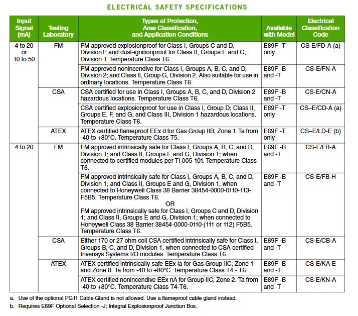
Electrical Explosion proof Safety Certification
Shell Type
B: Bolt fastening cover (weather resistant type): Used for non explosion scenarios, supports intrinsic safety and non flammable certification, and cannot be used for explosion applications.
Thread cover (explosion-proof shell): can be used in explosion-proof and explosion-proof scenarios.
Main certification:
FM: Explosion proof Class I Div1 C/D; Dust explosion-proof Class II Div1 E/G T6; Intrinsic safety; Div2 is non flammable.
CSA: Div2 non flammable; The T version supports Class I Div1 explosion-proof.
ATEX
– T configuration – J explosion-proof junction box: EEx d IIB Zone1 T5;
EEx ia IIC Zone0/1 T4-T6 (intrinsic safety); EEx nA IIC Zone2 (non flammable).
When using intrinsic safety, it must be paired with certified safety barriers/isolation modules. Explosion proof models cannot use PG11 horn cable glands, explosion-proof glands must be used.
Interface, Physics, and Optional Accessories
Electrical interface: 1/2-inch conduit thread; Pre connect 0.5m long 18AWG twisted pair cable at the factory; Multiple types of junction boxes are available for selection.
Pneumatic interface: Both gas supply and output are 1/4 NPT internal threads.
Standard aluminum nameplate with a maximum of 86 character tag numbers; Optional stainless steel external label MTS, with a maximum of 10 lines and 40 characters per line.
Optional accessories (model suffix/AS code)
Option Description
J-integrated explosion-proof junction box (only applicable to T-shell)
– M small junction box, 1/2NPT forward wire (cannot be used for – T explosion-proof shell)
– P small junction box, 1/2NPT rear line (cannot be used for – T explosion-proof shell)
The R comes with a filter pressure reducing valve (without a pressure gauge)
– S gas supply+output dual pressure gauge
MTS stainless steel external tag number plate
MB-A~MB-F PG11/PG13.5/M20 cable horn mouth with different incoming directions
Order coding rules
Format example: E69F-TI2-J Meaning: E69F (model) – T shell (threaded explosion-proof) – I input (4-20mA) -2 output (3-15psi) – J integrated explosion-proof junction box.
Shell: B-bolt cover (non flameproof)/T-threaded cover (flameproof)
Input type:
Additional information is required: range, positive/negative effects.
I: 4-20 mA (including split range 4-12/12-20mA) impedance 170 Ω;
H: 10-50 mA (including split range 10-30/30-50mA) impedance of 27 Ω;
Output code: 2/3/7/8
Optional suffixes – J/- M/- P/- R/- S
Additional AS code: MB-A~F (cable gland), MTS label;
Specify the electrical certification code.
Key points for filling out orders
Complete model;
Input range, positive/negative action;
Electrical explosion-proof certification;
All additional options (AS code);
User ID and application instructions.