Woodward easyYgen-3000XT series generator set controller
Product basic information
1. Model and hardware casing
EasyYgen-3500XT-P1/3500XT-P1-LT: plastic casing with LCD display operation panel; LT is a low-temperature version with built-in heating on the display screen, which automatically starts heating when the temperature drops below -20 ℃, increasing power consumption by 7.5W.
EasyYgen-3400XT-P1: Metal sheet metal casing, no local display screen, relying on LED indicator lights to display device status.
2. Applicable application scenarios
Support cogeneration, backup power supply, AMF automatic mains power fault switching, peak shaving, power input and output, and distributed generation; Supports islanding operation, islanding parallel connection, mains parallel connection, and multi unit mains parallel connection, managing up to 32 generator sets. It can control the generator circuit breaker GCB, the unit circuit breaker GGB, and the mains circuit breaker MCB, with comprehensive protection for the engine, generator, and mains. It supports interconnection and coordinated control with controllers of the same series and LS-5 systems.
3. Delivery includes items
Controller body, product CD (configuration software ToolKit, manual); Plastic shell with 4 snap fasteners; Sheet metal shell with 12 screw kit. The controller firmware stores PDF manuals and configuration files internally, which can be read through USB. However, the internal file version is not the latest, and the latest information needs to be accessed on the Woodward official website.
4. Hardware Interface Overview
Interface Type Description
Ethernet LAN A/B/C, 3-channel RJ45 network ports, used for communication and load sharing
CAN bus CAN # 1/# 2/# 3 three-way CAN; CAN2 supports J1939 engine ECU protocol
RS-485 serial port, supporting Modbus
USB 2.0 Slave Service debugging port, used for PC configuration debugging
Terminal block voltage PT measurement, current CT measurement, analog I/O, digital input DI, relay output DO, MPU magnetic pulse speed sensor, power supply, D+charging generator
Safety regulations
Applicable personnel: Must be qualified electrical technicians, familiar with on-site safety regulations, and familiar with power generation equipment.
Classification of hazard levels: DANGER (fatal danger), Warning (risk of fatal injury), CAUTION (minor injury), NOTICE (equipment and property damage).
Electrical safety
Power off operations must comply with the five electrical safety rules: power-off, anti closing, electrical inspection, grounding short circuit, and isolation of adjacent live parts.
Do not short-circuit fuses; The device is equipped with a built-in lithium battery to power the RTC real-time clock. On site users are prohibited from replacing the battery on their own and must contact the service provider.
ESD protection: Release human body static electricity before operating the terminal, wear an anti-static wristband; Unauthorized disassembly of the device casing is prohibited as it may result in loss of warranty.
Mechanical prime mover safety: The engine must be equipped with overspeed/overtemperature shutdown protection independent of this controller, and cannot rely solely on controller protection.
Safety relay: The relay output R01 defaults to “Ready for operation” at the factory and must be connected in series with an external emergency stop circuit; When the controller fails and loses power, the relay will disconnect, and the motor circuit breaker must be tripped and the machine must be stopped.
Maritime use: Metal shells default to meeting the requirements of classification societies; The plastic shell must be fixed and installed with a full set of 12 screws for maritime certification, and the buckle installation does not meet the requirements of maritime certification.
Power safety: It is recommended to use SELV safe ultra-low voltage power supply; DC power supply 8-40Vdc; Protective grounding PE cable ≥ 2.5mm ².
System Overview
1. Human machine interface HMI (plastic shell with display screen model)
Button grouping: mode buttons (STOP stop, MAN manual, AUTO automatic, TEST test), navigation software buttons, HOME home button, alarm confirmation button.
5 types of homepage display screens: generator, generator+mains power, generator+busbar, generator+engine parameters, generator+LS-5; Support custom customer screens, with software lockable buttons.
Light prompt: mode button backlight; Slow flashing of alarm triangle light=unconfirmed alarm, constant light=alarm confirmed but fault still exists, flash=firmware upgrade/factory reset in progress.
2. Metal shell version status LED
The dual color LED (red/green/orange) is divided into communication indicator light and operation indicator light, which respectively indicate the CAN bus communication status, device readiness, warning alarm, shutdown fault, and firmware burning status.
3. Application Modes
Provide more than ten application modes for A01-A11, defining the control capability of circuit breakers:
A01 None: No circuit breaker control, only collects measurements and starts/stops the engine.
A02 GCB open: Only trip the development motor circuit breaker.
A03 GCB: Generator circuit breaker opening and closing control.
A04 GCB/MCB: Generator+mains circuit breaker to achieve automatic switching of AMF mains faults.
A05 GCB/GGB: Generator+Unit Bus Circuit Breaker.
A06 GCB/GGB/MCB: All three are controlled by GCB/GGB/MCB.
A07~A11: Collaborate with the LS-5 system, with LS-5 serving as the master/slave to achieve multi system expansion.
4. Four operating modes
STOP stop, MANUAL manual, AUTO automatic, TEST test, equipment power on and internal initialization phase; External signals can lock panel buttons and prohibit local mode switching.
Hardware installation
1. Sheet metal shell (3400XT-P1)
Size: 227 mm × 250 mm, depth 50 mm; backplate screw holes, use M6 screws for installation, diagonally cross tighten. The protective grounding uses a dedicated grounding terminal at the bottom of the shell, and the 61 pin of the terminal block is not grounded.
2. Plastic casing (3500XT-P1/LT)
Choose one of two installation methods:
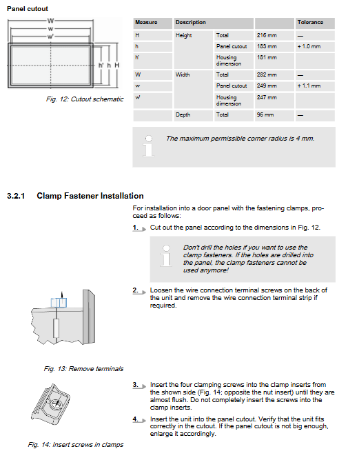
Clamping firmware: panel holes, clamp with buckles, no need to drill holes; This method cannot achieve IP66 protection level.
Screw kit: panel opening+12 screw holes, all screws tightened to achieve IP66 protection; Maritime applications must use this method.
Panel opening size: height 183mm, width 249mm, maximum rounded corner R4mm; The overall shape of the machine is 282mm × 216mm, with a depth of 96mm.
Terminal wiring
The maximum wire diameter of the terminal is 2.5 mm ²; Signal line recommendation: ≥ 90 ℃ temperature resistant cable; The length of the exposed shielding layer of CAN/RS485 shielded wire is ≤ 25mm.
1. Power supply
Terminal 63 (B+), 64 (B -), 8-40VDC DC; Terminal 61 is a protective grounding PE (plastic shell only); It is recommended to equip the circuit with a 6A slow melting fuse or a C6 miniature circuit breaker. Support instantaneous voltage drop during startup, capable of withstanding a short duration of 4.5V/50ms during startup. Charging generator D+: Terminal 65, used as pre excitation output during the start-up phase and as charging voltage monitoring input during normal operation.
2. Voltage measurement
Supporting generator voltage, mains voltage, and busbar voltage, supporting configurations: 3PH4W three-phase four wire, 3PH3W three-phase three wire, 1PH3W single-phase three wire, 1PH2W single-phase two wire (phase phase/phase neutral);
Generator voltage terminal: 30-36; Supply voltage terminal: 22-28; Bus voltage terminal: 38-40.
It is necessary to configure the PT voltage secondary side rated value in the controller parameters and match it with the voltage transformer. It is recommended to install a 2-6A slow melting fuse in the voltage input circuit.
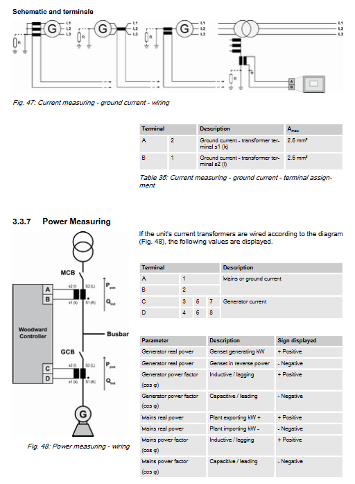
3. Current CT measurement
Important warning: Before disconnecting the CT secondary wiring, it is necessary to short-circuit the current transformer to prevent high-voltage injuries. The CT secondary side is grounded nearby.
Generator CT: Terminal 3-8, supports three-phase current measurement;
Commercial power CT: terminals 1-2; This channel software can switch to ground zero sequence current measurement.
CT secondary rated 1A or 5A, software parameter selection.
4. MPU magneto electric speed sensor
Terminals 79 and 80; The cable shielding layer is only grounded at a single point on the controller end, and the shielding on the sensor side cannot be grounded; The maximum input frequency cannot exceed 14kHz.
5. Digital input DI (DI01-DI12)
Electrical isolation, all DI must have uniform polarity (all positive logic or all negative logic); Configurable normally open NO/normally closed NC.
DI01 factory pre assigned external emergency stop signal: This input is only an alarm signal and cannot be used as a safety emergency stop according to EN60204 standard. The true emergency stop circuit must be externally hardware and cannot rely on a controller.
6. Relay output (LogicsManager programmable relay R01-R12)
A-type relay contacts, most functions can be customized through the LogicsManager logic manager; R01 is fixed as a device ready safety relay. Supporting the driving of 24V relays requires the addition of an absorption protection circuit. The output includes: starting motor, fuel valve, GCB/MCB/GGB opening and closing commands, centralized alarm, etc.
7. Analog I/O
Analog input supports resistance signals of 0-2000 Ω, 4-20mA, and 0-1V; Analog output supports ± 20mA, ± 10V, PWM output.
Equipment configuration
Two configuration methods: local HMI panel and PC ToolKit software; ToolKit has full parameter permissions, and some panel parameters are not visible.
Local HMI Operations: Home Page, Customer Custom Screen, Parameter Settings, Alarm List, Event History, Synchronization Table, LogicsManager Logic CAN、 Ethernet, USB, RS485, J1939 parameters.
PC ToolKit software: USB service port or Ethernet connection; Install software and EDS configuration files; Can read and write parameters, upload and download configuration files.
Basic settings: language, clock, HMI display, password permissions; Password grading management parameter access permission.
Engine configuration: start stop logic, MPU speed, idle speed, synchronous acceleration;
Input/output configuration: DI/DO, analog, LogicsManager logic programming;
Circuit breaker configuration GCB/GGB/MCB: opening and closing logic, synchronous grid connection parameters, neutral interlocking;
Controller regulation: voltage regulation, power factor control, load distribution, frequency PID, load start stop LDSS;
Monitoring and protection configuration (extensive ANSI standard protection):
Generator: Overvoltage, Undervoltage, Overfrequency, Underfrequency, Overcurrent, Overpower;
Engine: overspeed, underspeed, startup failure, shutdown fault, oil pressure, water temperature;
City power protection (grid connected application): over frequency/under frequency, over voltage/under voltage, islanding prevention (VDE-AR-N-4105 city power column), active and reactive power exceeding limits, phase sequence;
Measurement configuration: PT/CT ratio setting;
Interface parameters: USB, RS485 Modbus, three-way CAN (CAN2 supports J1939 engine ECU), Ethernet, SNTP time synchronization;
LogicsManager: Free logic programming, thousands of logical variables (alarms, DI status, system status, timers, etc.); AnalogManager is a simulation manager that processes analog operations; Counter maintenance running hours and service timing.
Equipment operation
Power on: self-test, screen lights up, enters the homepage.
Mode switching: STOP, MAN, AUTO, TEST; External signals can lock panel buttons.
STOP mode: Shutdown;
MANUAL Manual: Manually start and stop the engine locally, and manually open and close the circuit breaker;
AUTO automatic: fully automatic operation, AMF、 Load self start stop LDSS;
TEST test: with/without load test.
Application Cases
Basic standalone applications: AMF, standalone grid connection.
Multi unit application: up to 32 units, load on-demand start stop LDSS, load sharing, emergency mode, power control.
Special applications: excitation protection, analog quantity setting, pulse relay, remote start stop confirmation, CAN extended IO, phase angle compensation, neutral interlocking, speed synchronization and grid connection.
CANopen remote control: remote start stop, remote issuance of voltage/frequency/power/power factor set points.
Modbus applications: remote control, reading and writing parameters, remote confirmation of alarms, clearing event records.
Interface and Communication Protocol
CAN bus three-way division of labor:
CAN1: System Coordination;
CAN2: Engine layer, J1939;
CAN3: Multi unit system layer.
Ethernet: Three independent Ethernet channels, supporting UDP broadcasting for load sharing.
Protocol: CANopen, J1939 engine protocol Modbus RTU(RS‑485); Load sharing supports two methods: CAN bus or Ethernet UDP.