Woodward SOGAV ™ 250 solenoid valve drives gas intake valve
Basic Security and Compliance
1. Safety warning classification
DANGER: Failure to avoid will result in death or serious injury;
Warning: There is a potential risk of death or serious injury;
CAUTION: Minor/moderate injury;
NOTICE: Only causes damage to equipment and property.
Key mandatory safety points
The engine must be equipped with overspeed shutdown and fuel cut-off protection devices that are completely independent of this control system, and cannot rely on SOGAV valves for safety protection.
Explosion proof hazardous area: It is prohibited to plug or unplug wiring in a live state, unless the confirmed area is a non hazardous area; Replacing non original components will damage the explosion-proof certification.
Personal protective equipment must be worn during homework: eye protection, hearing protection, safety helmet, protective gloves, safety shoes, respirator; Read the Material Safety Data Sheet (MSDS).
ESD protection for static electricity: The internal static sensitive components of the equipment should release human static electricity before operation, and it is forbidden to touch the conductors of the circuit board with bare hands.
The product casing may experience high/low temperatures during operation, and protective tools must be worn during operation.
After shutdown, the gas manifold must be depressurized and emptied to prevent valve leakage from causing fuel to fail during the next start-up.
2. Compliance certification
European CE
ATEX Explosion proof: Zone 2, Class 3, IIG,Ex nA IIC T3 X Gc,IP54;
Low Voltage Directive 2006/95/EC;
Belongs to unfinished mechanical components that comply with the Machinery Directive 2006/42/EC; the EMC Directive does not apply to this passive component.
North American CSA certification: Class I, Division 2, Groups A/B/C/D, T4 (environment 105 ℃).
Mandatory wiring requirements: on-site cables must withstand a temperature of ≥ 105 ℃; The grounding terminal of the valve body must be connected to a protective ground.
Product principle
Driving principle: E-type iron core electromagnet drives low-carbon steel armature; The fully closed to fully open stroke of the valve is only 0.50mm, with short stroke, high output magnetic force, and fast switch response.
Valve core structure: Multi concentric circular groove disc lift valve. The dynamic metering disc relies on a spring and medium pressure to tightly seal the cover and achieve closure; Electromagnetic iron is energized to attract the disc, with grooves staggered and gas flowing through; The electromagnet is powered off, and the spring+medium pressure difference quickly closes the valve without sliding wear.
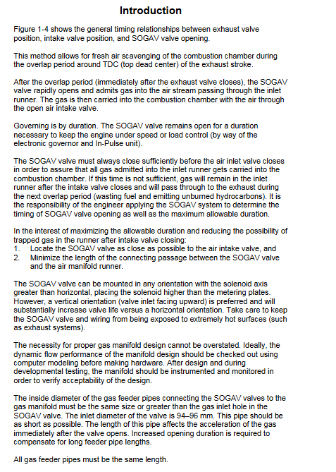
Working sequence: After the top dead center (TDC) sweep overlap of the exhaust stroke is completed, the SOGAV quickly opens and must be completely closed before the intake valve closes to avoid residual gas in the manifold and unburned hydrocarbons being discharged to the exhaust side. Control the gas volume by relying on the duration of valve opening (time regulation).
Special requirements for electrical drive: cannot be continuously driven by ordinary DC power supply; Must have a dedicated two-stage current drive controller (In Pulse/LECM/ECM3): the first stage has a large pull in current, and the second stage has a small hold current; It is necessary to control the equivalent average DC EADC and equivalent average power EAP to prevent coil overheating and burnout.
Installation and Initial Debugging
Prerequisite for installation: The interior of the intake manifold must be thoroughly cleaned, free of welding slag, metal debris, and impurities that can cause sticking and damage to valves and engines.
Seal: Use FKM (Viton fluororubber) O-ring, refer to Parker O-ring manual.
bolt tightening
Valve body installation to cylinder head/intake manifold: M10 or 3/8 hexagon socket screws, evenly diagonally locked according to the engine manufacturer’s torque.
Gas inlet pipeline M8 × 1.25 thread, with at least 10 teeth engaged and a torque of 20 N · m.
Valve body installation posture: The axis of the electromagnet is greater than horizontal, and the position of the electromagnet is higher than the measuring disc; Prioritize vertical upward intake installation, significantly extending lifespan; Stay away from high-temperature components such as exhaust pipes.
Grounding: The grounding terminal of the valve body should be reliably grounded to the ground.
Finally assemble the cable connector and tighten the roller nut.
There are no mechanical adjustment points on site, they have already been adjusted at the factory.
Leak detection after installation: Introduce dry air/inert gas and soap water to check for flange and interface leaks; In a quiet environment, you can hear the sound of the valve ticking to confirm the basic action.
Application Design Guidelines
1. Key points of pipeline and manifold system design
SOGAV should be placed as close as possible to the intake valve and the connecting pipeline should be shortened; All gas supply branch pipes leading to each cylinder valve must have exactly the same length; The inner diameter of the branch pipe is greater than or equal to the valve inlet aperture (94-96mm); It is recommended to use flexible pipelines for branch pipes to avoid mechanical stress on the valve body caused by rigid welded pipelines.
The gas main has sufficient volume to reduce pressure loss and suppress pressure pulsation; Multiple intake points to prevent insufficient remote air supply when multiple valves are simultaneously opened.
Valve body installation opening: aperture 95-110mm; aperture too small to limit flow, aperture too large to ensure disc stress.
Pressure difference hard limit: The maximum allowable pressure difference Δ P on both sides of the valve is 150 kPa (1.5 bar). If the pressure difference exceeds this value, the valve cannot be opened.
The control system must simultaneously control the intake manifold pressure and gas manifold pressure to ensure that the pressure difference is within the allowable range.
Do not add too much gas dispersion device in the intake manifold, as it will throttle and trap gas.
2. Wiring specifications
The wiring requirements vary depending on the controller used
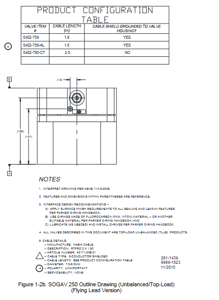
Paired with Woodward In Pulse II/ECM3 controller: twisted pair shielded cable, with the shielding layer only grounded on the controller side, and the SOGAV end shielding must not be grounded. Non grounded cable glands are used. Cable selection:
|Cable length | Cable diameter|
|≤15 m |1 mm²(18AWG)|
|15‑25 m |1.5 mm²(16AWG)|
|25‑40 m |2 mm²(14AWG)|
Paired with LECM controller: No need for shielding, use twisted pair cables with ≥ 30 twists per meter; Cable<10 meters shielded can be connected to LECM; The 10 meter shielding is only grounded at the valve body end.
The grounding terminal of the valve body must be grounded.
3. Valve selection flow calculation formula
\(Ma:=Z \cdot \sqrt{\frac{k \cdot 2}{(k-1)} \cdot sg \cdot\left(P_{1}\right)^{2} \cdot\left[\frac{293.15}{\left(273.15+T_{g}\right)}\right] \cdot\left[\left(\frac{P_{2}}{P_{1}}\right)^{\frac{2}{k}}-\left(\frac{P_{2}}{P_{1}}\right)^{\left(\frac{k+1}{k}\right)}\right]}\)
Z=215 (SOGAV-250 valve constant); Ma: Gas mass flow rate g/s
k: Specific heat ratio Cp/Cv; SG: gas to air ratio; P1 upstream absolute pressure bar; P2 downstream absolute pressure bar; Tg gas temperature ℃
When P2/P1<0.544, congestion occurs and forced substitution into 0.544 is calculated.
4. System security
After the engine is stopped, the gas manifold must be depressurized; Once a leak is detected, immediately shut down and blow the fuel system to confirm the source of the leak. If the valve is damaged, replace it directly.
Maintenance and troubleshooting
Factors affecting valve lifespan: engine speed, fuel impurities, filtration accuracy, temperature, vibration, drive controller, fuel oil content (minimum recommended 2ppm oil content, special coating version required below 2ppm), installation posture. It is recommended to prioritize sending it back to Woodward’s original factory for maintenance; Unauthorized disassembly will result in the loss of all warranty.
The four fault tests (performed in sequence after removing the valve) all passed, indicating that the valve body has no faults. The problem lies in the external controller, cables, and system pressure difference.
Room temperature coil resistance: 1.1-1.3 Ω; Compensate for the resistance of the multimeter probe during measurement.
Coil to ground insulation: close to infinity; If the resistance is low and the coil is short circuited to ground, replace the electromagnetic component.
Coil integrity testing
Leakage test: Apply 150kPa compressed air at the inlet; Leakage flow rate<2.83 m ³/h (100SCFH); A large leak indicates that the disc is damaged or there are impurities in the middle.
Electromagnetic attraction force test: 110VDC, 16A current limiting power supply; The power pulse must not exceed 2 seconds, and the interval between two pulses should be cooled for one minute; Hearing a loud “explosion” indicates that the suction force is qualified.
Valve core stroke measurement: measure disc displacement when powered on or off; Standard travel 0.49-0.52 mm (0.0193-0.0205 inch); Travel too small, impurities stuck; Parts wear due to excessive travel.
External fault point troubleshooting: valve pressure difference exceeds 1.5 bar; The total resistance of the cable circuit is greater than 0.4 Ω; Cable overheating; Virtual connection of connectors.
Technical specifications
1. Environmental parameters
Working temperature: Two model series are respectively -20~+105 ℃/-20~+95 ℃; Storage -40~+70 ℃
Protection level IP66; Maximum altitude of 4000 meters; humidity ≤ 85% without condensation; Resistant to salt spray and high-pressure flushing.
2. Performance indicators
Fully open response time: maximum 5 ms; fully closed response time: maximum 5 ms.
Close leakage: less than 0.25% of steady-state fully open flow.
Fuel filtration: absolute accuracy of 5 μ m.
Allowable gas pressure: upstream maximum 4.5 bar absolute pressure; Downstream maximum 3.0 bar absolute pressure; The maximum pressure difference is 1.5 bar.
Resistance to tempering impact: 0.5 bar higher than the gas manifold pressure; An impact exceeding+2 bar can damage the valve.
The maximum temperature of the intake medium is 80 ℃.
3. Fuel medium requirements
Support natural gas, coalbed methane, coal mine ventilation, biogas, and associated gas; Restrict hydrogen sulfide, ammonia, halogens, and solid particles; The maximum size of solid particles is 5 μ m; Prohibit chemical media such as acetone and ethyl acetate, as they may corrode and damage valves.
Interpretation of Electromagnetic Valve EADC/EAP Rating
SOGAV-250 must be driven by two-stage pulse current: Ip draws in high current and Ib maintains low current.
EADC equivalent average DC current: Based on I ² R heating, calculate the equivalent continuous DC waveform of the periodic current waveform, which cannot exceed the rated value on the nameplate to prevent coil high temperature.
EAP equivalent average power=EADC ² × Rc; Rc is the maximum high-temperature resistance of the coil.
Provide EADC calculation formulas, waveform diagrams, and maximum high-temperature resistance meters for various types of coils.