Allen Bradley IntelliVAC 1503VC Series E Control Module
Product Description
1. Core functions
Wide control power supply: AC 110-240 V 47-63Hz/DC 110-250 V.
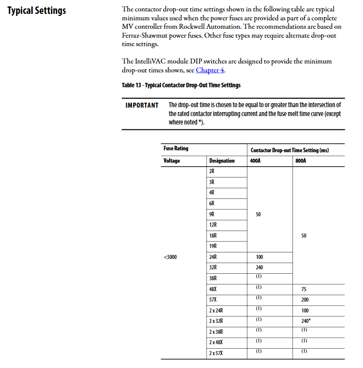
Good consistency of contactor closing time; Configurable contactor trip Drop out time to achieve selective coordination with upstream high-voltage fuse protection.
Altitude compensation: The 400A contactor supports electronic DIP altitude compensation (-1000~5000m); 800A relies on mechanical spring adjustment and DIP fixed setting of 1-1000m gear.
TDUV delayed undervoltage crossing: Short term voltage drop/brief power loss maintains contactor closure, external electrolytic capacitor prolongs holding time.
Protection logic: anti kiss bulletproof jump, anti pumping anti reverse composite gate; Delay restart protection contactor operation cycle; The jog JOG function only supports electric holding contactors.
2. Comparison of iterations across different versions
Series features
A is divided into two models, driving EH and ML respectively, and has now been discontinued
B single module supports both EH/ML, discontinued
Improved version of C B, firmware 2.003
D Fault and warning logic firmware enhancement, firmware 3.001/3.002, discontinued
E hardware redesign, cancellation of Mini DIN debugging port; Anti leakage current input; Firmware 4.004+; Firmware upgrade relies on Plus/MC expansion board; This manual describes the object
3. Electrical and mechanical specifications
Electrical
Closing peak impulse current of 25A; distinguish between suction current, holding current, and mechanical lock release pulse current;
Action threshold: suction minimum 95VAC; Release 75VAC; Mechanical lock release: 400A minimum 70VAC, 800A minimum 80VAC;
Command input: 70-240VAC/70-250VDC, optimize PLC leakage current;
Status relay output: AC250V 5A resistive; DC30V 5A resistive.
environmental parameters
Working environment temperature: 0-60 ℃; Altitude>1000m, with a decrease of 2 ℃ for every 1000m increase, and a maximum usable height of 5000m;
Storage -40~85 ℃; Humidity ≤ 95% without condensation; Pollution Level II; Resistance to Vibration and Shock;
Certification: CE, cULus, CSA.
Dimensions: 185.3 × 165.9 × 59.4 mm, fixed with two screws.
Reception and Storage
Upon receiving the goods and opening them for inspection, if there is any damage during transportation, immediately report it to the carrier; If it is a complete set of 1500/1900 cabinet built-in modules, follow the complete equipment manual.
Storage conditions: clean, dry, and dust-free; ‑40~85 ℃; Relative humidity ≤ 95%, no condensation.
Installation and Wiring
Electrostatic sensitive devices must be operated with ESD protection; Only for certified electrical personnel undergoing training; Follow NEC and CEC local electrical specifications.
3-1 Two application forms
Integrated built-in: As an original built-in component of the 1500/1900 medium voltage control cabinet.
OEM independent supply:
Reserved ventilation gap above and below ≥ 38.1mm; minimum distance between multiple units arranged side by side is 6.4mm;
OEM responsible for: external fuses, motor overload protection, start stop buttons, contactor wiring harness, TDUV capacitors; CE certification requires the configuration of EMC filters.
3-2 Grounding
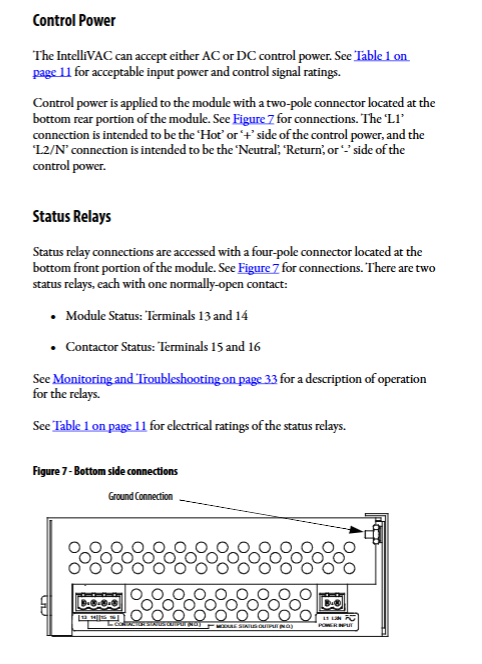
The grounding terminal of version E is located at the bottom of the module casing; The cabinet must be connected to the PE public protection ground, as poor grounding can cause equipment damage and personal injury.
3-3 External fuse selection (mandatory external configuration)
The AC circuit uses TRM delay fuses; The DC circuit must use ATM fast melting that can break DC.
When using shared fuses or external TDUV capacitors, it is necessary to select the largest specification fuse in the table to prevent melting due to power on impact.
Recommended types of power contactors: fuses
110‑120VAC 400A EH TRM2‑TRM3.2; 800A EH TRM2‑6.25A; ML TRM2‑3.2
220-240VAC all types TRM2-6.25A
125/250VDC EH/ML ATM3‑ATM6
3-4 terminal interface definition (3 sets of green quick plug connectors)
Power connector (bottom): L1 (+), L2/N (-/N).
Status relay (4-pole, bottom), all normally open NO:
13-14: Module status; Fault disconnected, normally closed.
15-16: Contactor status; The contactor closes after closing.
12 pole top interface
Pin Definition Explanation
1. 2 EC external capacitor TDUV/capacitor trip
3. 4 TCO release coil mechanical lock release output
5. 6 CCO closing coil EH/ML closing output
7. 8 OPEN/JOG input open/jog command
9. 10 CLOSE command input closing command
11. 12 AUX auxiliary feedback contactor auxiliary contact feedback (normally closed)
3-5 Control Wiring Scheme
① Electric holding contactor EH
Two line control: Long level maintains closing; To clear the fault, the closing signal needs to be removed for at least 4 seconds before reapplying; DIP can close the power on safety lock (not recommended, there is a safety risk).
Three wire control (start stop button+self-locking): START instantaneous closing, STOP opening; Use contactor status relays for self-locking.
Temporal Hard Constraints:
The minimum interval for normal closing instructions is 6 seconds, and the rated operating cycle of the protective contactor is 600 times per hour;
It is recommended to wait for 4 seconds before sending the closing command when the module is powered on;
When the power on safety DIP is turned on, the power on detection contactor has already closed and refuses to close. The module must be powered off and restarted.
Solid state PLC output driver attention point E version optimizes leakage current; If the leakage current of the PLC transistor/three terminal bidirectional thyristor output exceeds the standard, an intermediate isolation relay must be added to prevent misoperation.
② Mechanical lock contactor ML
Both closing and opening require a pulse signal of ≥ 50ms, and there is no need to maintain a voltage level.
Capacitor Trip: Control power loss and rely on external capacitor energy storage to output trip pulses to disconnect the contactor;
The maximum capacitance of the 120V system is 1650 µ F, and the withstand voltage is ≥ 200VDC; The maximum voltage for a 240V system is 330 µ F, with a withstand voltage of ≥ 400VDC;
After losing power, the OPEN disconnection command must be given within a few seconds. If the capacitor energy is exhausted after the timeout, it cannot be tripped.
③ JOG jog (only limited power to maintain EH)
Use OPEN terminal to achieve jog; Close the valid contactor and immediately disconnect it upon cancellation; Bypass 6s restart delay, specifically designed for debugging and alignment.
④ TDUV delay undervoltage crossing function
Short term voltage drop maintains contactor closure;
No external capacitor: 110-120V maximum 0.2s; 220-240V maximum 1.0s;
External EC capacitor, combined with DIP switch, can be set to maintain power loss for up to 2 seconds.
Important safety warning: When TDUV is enabled, if the control power of module L1 is cut off, the contactor will not immediately open and will wait for the TDUV delay to end before disconnecting, which is not suitable for emergency stop circuits that require immediate power outage; PF7000 with STO safety torque closing input contactor, TDUV cannot be set for more than 0.2 seconds.
Under voltage triggering condition: Within 200ms after closing, the voltage is less than 90V; after 200ms, the voltage is less than 72V, and TDUV timing starts. If the contactor trips and reports a fault after exceeding the time limit.
Setting and Debugging Commissioning
To modify DIP dialing, the module power must be completely disconnected and external capacitors must be discharged; After modification, DIP settings will only take effect when powered on again. Disassembling the casing reveals high pressure inside. The E version uses a 16 bit DIP switch located at the front edge of the circuit board. DIP configuration items: altitude compensation, contactor trip Drop out time (50-240ms), contactor type 400/800A EH/ML, TDUV enable, external capacitor TDUV duration, power on safety enable.
Factory default parameters: altitude 0-1000m; trip 130ms; 400A electrical hold EH; TDUV off; Power on safety activation.
The complete set of 1500/1900 has been pre configured before leaving the factory; Individual ordering modules use default parameters, and DIP must be checked before powering on.
Firmware upgrade: E version no longer supports Mini DIN port; An external IntelliVAC Plus/IntelliVAC MC auxiliary board is required to complete the firmware upgrade.
Monitoring and Troubleshooting
Panel dual LED indicator lights:
Module Status module status light (flashing green/red/yellow): Green is normal; Red=unrecoverable fault (power off reset); Yellow flashing=warning (automatic recovery upon condition elimination).
Contactor Status contactor status light (yellow): It lights up when receiving a closing command and the contactor is closed.
E version distinguishes between warning (automatic recovery after condition elimination) and fault (module must be powered off and restarted); Support multiple sets of flashing fault codes.
Typical fault phenomena
The contactor does not operate at all: there is no control power supply; External protection (overload, emergency stop) action; DIP configuration error; The internal fuse is blown; The plug is loose.
The contactor briefly closes and then refuses to close: the coil is damaged; Auxiliary contact assembly adjustment error; Voltage drop triggers undervoltage fault; Foreign object stuck on the armature; Power off reset is required.
Unjustified disconnection during operation: overload protection, stop command; TDUV timeout undervoltage; AUX auxiliary feedback abnormality.
The mechanical lock cannot be released: the minimum working voltage is not met; Damage to the release mechanism; Loose wiring.
Spare Parts and Options
Material Model
1503VC-BMC5: Series-E module body;
Internal insurance: 6.3A-250V Littlefuse 21506.3;
Connector spare parts: 2-pole power supply, 4-pole status output, 12 pole I/O connector.
option
TDUV electrolytic capacitor: 120V (1650 µ F)/240V (330 µ F), with bracket terminal shield;
EMC filters are used for CE EMC compliance.