ABB Advant Controller 160 (AC160) DCS System Specific S600 Series I/O Module
Introduction
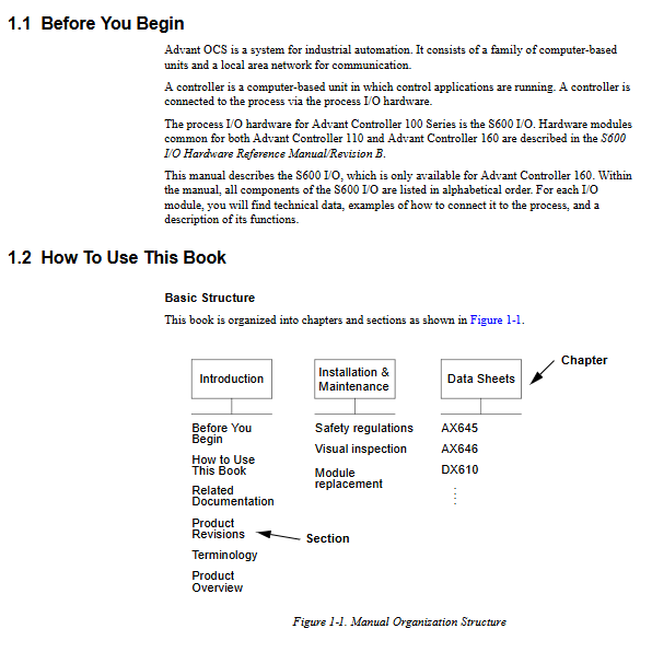
System positioning: Advant OCS is an ABB industrial automation system; The Advant Control160 (AC160) controller relies on S600 I/O to complete on-site signal acquisition and output; The S600 is also compatible with the old AC110 controller, but this manual only covers AC160 specific modules.
Installation and Maintenance
2.1 Safety Regulations
Hazard classification
DANGER: Can cause fatal and serious injuries; Warning of personal injury; CAUTION equipment is damaged; NOTE Reminder Precautions.
Personnel and Process Safety
Qualified lifting equipment must be used for cabinet hoisting; The wiring maintenance must be powered off; The system supports remote start stop and configuration modification through AF100 fieldbus; The controller can automatically start the program when powered on, and the START MODE needs to be set to STOP to prevent self starting.
Machine hardware safety – ESD electrostatic protection
All static sensitive components on the circuit board; Grounding wristband must be worn during operation; Store in a conductive anti-static bag when not in use; Welding operations require the module to be pulled out by at least 20mm; the cabinet is labeled with ESD warning labels.
2.2 Visual Regular Inspection
Check screw tightening, insulation aging and overheating; Clean the cabinet dust with compressed air/dust-free cloth; The air filter should be cleaned regularly and must be replaced after 3 washes; Check the forced cooling system of the fan.
2.3 Module hot swappable replacement (online replacement)
S600 supports online replacement of IO modules without stopping, but the process risk caused by signal loss needs to be evaluated!
Unplug the process connector, the system automatically detects, the RUN green light goes out, the output switches to the safe position, the database element ERR is set to the fault position, and the refresh signal VALUE value stops.
Replacement steps: Open the front door and remove the signal label paper strip; Loosen the screws of the process connector and unplug the plug; Loosen the fixing screws of the module and pull out the old module; Insert a new module of the same model; Secure module screws; Insert the process connector back and tighten the screws; Module self-test, the FAILT red light briefly goes off, the RUN green light is on, the fault flag is reset, and work is restored.
Attention: It is recommended to isolate the process circuit on site before replacing the output module; The replacement of bus expansion modules CI610/CI615 will affect the I/O of the entire station.
Detailed Data Tables for Each Module
3.1 AX645 Configurable Hybrid Analog IO Module
16 channels, each channel software independently configured with 4-20mA analog input or analog output; Group isolation, no inter channel isolation within the group
Signal processing:
AO output: 14 bits; AI input 16 bits; Isolation voltage withstand 500VAC;
The conversion period varies with the number of activated channels; Supports 50/60Hz grid filtering that can be turned off;
AO comes with closed-loop feedback monitoring: compare the set output current with the actual sampling value, and report a fault if the deviation exceeds the limit; Support short circuit detection.
AI supports live zero disconnection detection; Supports 2-wire transmitters (onboard 24V power supply) and 3-4 wire external power supply transmitters.
Working mode: Each channel has independent AI or AO.
Fault diagnosis: AO signal deviation, short circuit, BIOB communication memory refresh timeout; AI live zero error (cable breakage).
Database DB elements
AX645: Basic parameters of the module (station number, slot position, grid frequency);
AXOS645 (output channel): activation flag, preset value of fault safety SP_VAL, signal deviation SIG_deV, minimum output voltage MIN_VAL, communication monitoring CMVNet, etc;
AXIS645 (input channel): Channel activation, filter switch, active zero threshold LZ_LIM.
Electrical: Maximum load resistance of 600 Ω; Power consumption of 8W; provide a complete wiring schematic.
3.2 AX646 Analog Input+Internal backtesting module
16 channels of 4-20mA analog input, equipped with 16 internal test DA outputs; The DA output is not externally connected and is only used for internal circuit self-test of the board.
Three modes: analog input, analog output (internal), and input test mode. In test mode, the DA output signal is directly fed back to the AI board to achieve channel hardware self-test, while the external power supply of the transmitter remains constant.
Performance: AI16 bit, DA14 bit, total conversion time<16ms; isolation 560VAC; Supports 2-wire/4-wire transmitters; Each channel can switch 50/60Hz filtering.
Limitations: Test mode cannot be shared by multiple CPUs simultaneously; Support high and low dual limit+hysteresis threshold check, generate alarm when exceeding limit.
Database elements AX646, AXIS646, AXOS646; Support online hot plugging.
3.3 CI610/CI615 I/O Expansion Bus Adapter (BIOB Bus Expansion)
AC160 system: One Basic base station can expand up to seven I/O slave stations; Relying on CI615 (base station side), CI610 (I/O slave station side), TK610 expansion cable, and TC610 bus terminal resistor. Supports single or dual redundant expansion buses.
CI615: Installed on the CPU Basic Station as the main terminal of the expansion bus; Status: RESET reset, PASSIVE passive, ACTION activated.
CI610: Installed on the I/O expansion station as an extension bus slave; I/O station addresses 1-7 must be unique;
Redundancy mode: two sets of CI615-CI610+two sets of TK610 cables; Automatic fault switching, with a switching time of less than 100ms; the software will periodically perform active primary backup switching tests to verify that the backup link is intact.
Hardware monitoring: Cable breakage, missing terminals, and undervoltage detection of backplane power supply; RUN/AULT/TRANSFER three status LEDs;
Accessories: TK610 bus cable 2.5/5/10m; TC610 bus terminal (the last I/O station must be connected to the terminal);
The maximum cable length is 20 meters, with a point-to-point topology, and branching is prohibited. No hardware dialing, completely relying on DB database configuration; Support online replacement.
3.4 CI630/CI631 Advant Fieldbus100 (AF100) fieldbus coupler
AF100 is ABB DCS control fieldbus, CI630 coaxial cable version; CI631 twisted pair version; AC160 controller basic station slot 2 must be equipped with at least one CI630/CI631.
Ability: Implement process data and service data exchange between AC160 controller and various stations on AF100 bus; Support bus master station and time synchronization master/slave mode; Support single module or primary/backup redundant configuration; You can configure the second slave AF100 bus.
CI630 (coaxial 75 Ω): up to 80 stations;
CI631 (twisted pair): up to 32 stations.
Redundancy mechanism: The Primary module continuously updates all data in the Backup module; Periodic automatic switching test; Main module failure without disturbance switching; Backup site address=main site address+80, with address limit constraint.
Function: Token passing bus master station rotation; AF100 full network time synchronization; Hardware mutual monitoring; Detect power failure, hardware fatal failure, and loop data not updated.
LED status: FAULT, RUN, TRAFFIC, MASTER, CONFIG-OK, REDUNDANCY, PRIMRY, BACK;
Compatibility: CI630 can coexist with CI626 on the same coaxial bus; CI631 and CI627 coexist on twisted pair bus; The same physical interface cannot mix models. Support online hot plugging.
3.5 DI685 32 channel digital input module
32 point isolated digital input, 4 sets x 8 channels; Supports 24VDC/48VDC sensors; Two working modes: regular DI and SOE event sequence recording (millisecond level timestamp, caching 64 events).
Key Features
Each board can turn off the 48V sensor power supply and support external sensor power supply;
Diagnosis of broken/short circuit lines in each channel (requires parallel connection of 47k Ω resistors);
Digital anti shake filter 0-255ms configurable; SOE mode with shutter filter to prevent event buffer overflow;
Optoelectronic isolation 500VAC; The maximum cable length is 1000m;
Database DI685, DIS685; Support online replacement; RUN/AULT module status LED+32 channel status yellow LED.
3.6 DP640 Dual Channel Speed Measurement Pulse Counting Module
Special speed measurement module for steam turbine/rotating machinery, with two speed measurement inputs.
Input support: 24V high impedance analog, 5V TTL, RS485 differential eddy current probe, gear pulse signal, up to 50kHz. Onboard multi-channel sensor power supply:+24V,+12V,+5V, -24V, with short-circuit/open circuit monitoring.
Two measurement modes
High Precision mode: Measure the speed according to the complete cycle of the gear disc, with high accuracy;
High Speed mode: Fixed measurement cycle, fast response.
Built in functions
Peak Hold memory maximum speed for peak maintenance;
Steering discrimination (channel 1+channel 2 phase);
Monitoring of sudden changes in speed gradient (suppressing interference jumps);
Hardware overspeed trip TRIP relay output, shutdown Standstill relay, ready Ready for Operation relay output; Software can trigger overspeed self-test without modifying the actual measurement values.
Rich diagnosis: sensor disconnection, insufficient signal amplitude, power supply failure; Database DP640 parameters: number of teeth, nominal speed, high and low speed limits, hysteresis, maximum speed gradient; Support online replacement.
3.7 DX610 Boiler Protection System Dedicated Digital IO Module
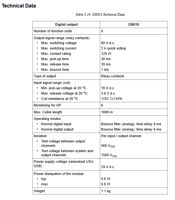
Used for boiler protection tripping actuator, equipped with PM646 processor, 6 functional units, each unit has 3 isolated relay contacts, and can achieve two out of three logic output.
Each relay auxiliary contact feedback reads back to the internal DI for circuit diagnosis; Equipped with a global second shutdown safety path, the external hard wire triggers the disconnection of all 6 unit relays.
Relay parameters: maximum 60VDC, 2A; Isolation withstand voltage 1500V;
Application: Boiler protection safety circuit; Provide a complete safety application wiring diagram; Support online hot plugging.