ABB SACO 16D1 alarm light plate unit
Product Overview
Core hardware capability
16 alarm input channels, capable of connecting to normally open NO/normally closed NC passive field contacts; It can also be configured as a pulse counting mode.
4-channel auxiliary relay output: 2-channel configurable group alarm flashing relay, 1-channel audio (horn/buzzer) driver, 1-channel internal self-monitoring fault output.
Four digit digital display, supporting first alarm indication, event browsing, and parameter configuration display; High brightness LED light indication for each channel.
Built in event cache: Local panel can read 9 entries; The SPA bus can read up to 50 relative timestamp event records with a time resolution of 5ms.
Protection: Panel installation back cover IP54; EEPROM stores all parameters and does not lose parameters in case of power failure.
Application scenarios: power plants, substations, factory process monitoring, offshore platforms, water treatment, monitoring of important building equipment; It can run independently on a single machine and also connect to the SPACOM protection control system backend.
Hardware modular structure (Euro card specification 100 × 160mm)
SPGU-240A1/SPGU-48B2: Power module, dual power input;
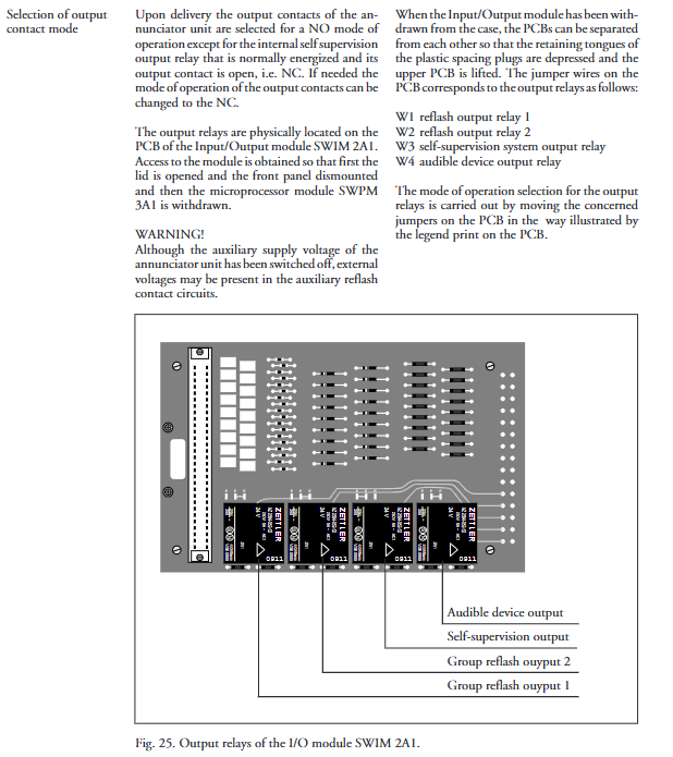
SWIM 2A1: IO relay input/output module;
SWPM 3A1: Alarm processing main control board;
SWCM 3A1: Back wiring terminal connection module;
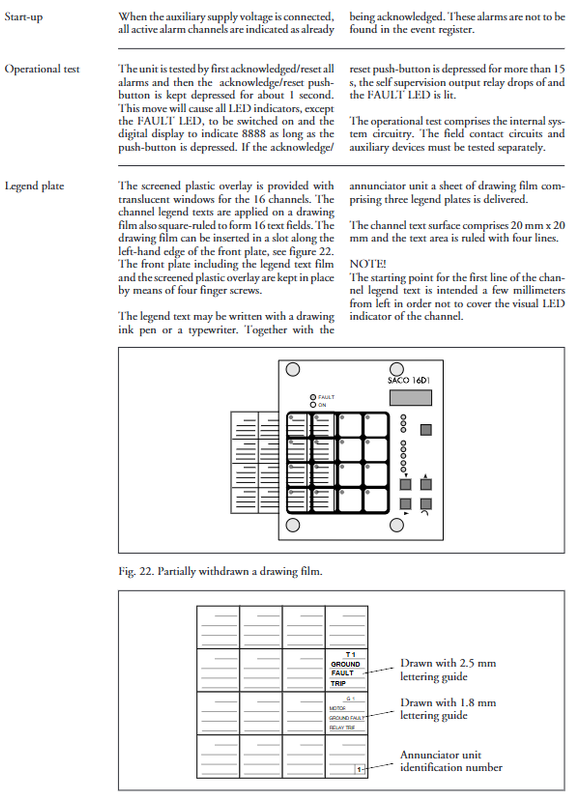
Aluminum profile shell, transparent lockable PC panel cover, matched with optical label film that can be written.
Power supply: SPGU-240A1 supports 80-265V AC/DC; SPGU-48B2 supports 18-80V DC; Internally generate isolated 48VDC for the on-site alarm contact circuit, without the need for external power supply to the contacts.
Input channel function
Each channel hardware is equipped with transient suppression and optoelectronic isolation, and provides an internal 48V detection voltage.
1.7 input signal modes (software configuration)
0: Normally open contact with return; 1: Normally closed contact with return; 2: Only triggered by rising edge; 3: Only triggered by the falling edge; 4: Rising+falling edge; 5: Contact closure pulse counting; 6: Contact disconnection pulse counting; 7: Count both opening and closing.
The maximum frequency of pulse counting is 3Hz, with a counting range of 0-29999. The power-off count value is lost and can only be read or written through the SPA bus.
2. Channel delay parameters (independently set input delay and reset delay)
Optional gears: 5 ms, 20 ms, 100 ms, 1 s, 5 s, 20 s, 60 s, 160 s; other times can be customized for the serial port.
Delay is used to filter out contact jitter; The status must continue beyond the set delay to determine a valid event.
3. Interlocking function
The whole machine provides 8 sets of internal interlocking buses; Each channel has: 1 interlocking output and 2 interlocking inputs.
Input type 1: Only block the re flashing A signal of this channel;
Input type 2: Block the entire channel; After the interlock is cancelled, the alarm status changes to “confirmed alarm”;
Input type 3: Block the entire channel; Generate a new alarm after the interlock is revoked.
Interlocking levels greater than level 3 will reduce the accuracy of event timestamps.
4. Contact jitter (Pumping) monitoring
You can set the maximum allowed number of events per minute for a single channel; The channel has been locked beyond the threshold, and the panel prompts that it needs to be reset and released to prevent frequent shaking and screen flashing of the contacts.
Alarm operation sequence (5 sets of standard specification sequences, globally selected for the entire machine)
Support ISA standard and DIN 19235 standard alarm logic: 0 ISA A: automatic reset; 1 ISA A-1: Automatic reset, separate sound cancellation for the audio system; 2 ISA M-1: Manual reset, audio separately muted; 3 ISA R-1: Manual reset, display when restored to normal; 4 DIN 19235: Echo logic.
Single channel can also be modified locally: follow the global sequence/trigger the sound when restoring normal/only follow the silent light alarm at the contact point.
Operation button logic
SILENSE Mute: Only turn off the audio output; ACK confirmation: Confirm the alarm; RESET reset: Clear the light character after the alarm condition disappears. Press and hold the panel buttons for 1 second to perform a full LED display test; Long press for 15 seconds to simulate an internal fault triggering the action of the self-monitoring relay.
Support external passive contact remote: remote mute, remote confirmation reset.
First out instruction
The first alarm channel to arrive after reset, the digital display shows the A channel number, records the first alarm of the accident occurrence, and is used for fault tracing.
Event Register
Local storage of 9 items, with panel buttons flipping through them one by one; Lost due to power outage.
SPA-BUS remote 50 loop cache with relative timestamp 0-60s; overflow marked matrix register without losing channel displacement information.
Output relay function
All 4 relays are located in the SWIM2A1 module, and the normally open/normally closed mode can be modified through jumper wires on the board. The factory default is:
Heavy flash group 1 and heavy flash group 2: Each channel can allocate two A/B heavy flash signals to two groups. Heavy flash mode is optional:
FCFR follows the contact state; AACR confirms controlled; ISR300ms pulse; Combination mode.
Audio output relay: any channel alarm action, driving buzzer and electric horn; Mute command to turn off output.
Self monitoring fault relay: normally energized and engaged; When the internal hardware, power supply, and 48V contact circuit are abnormal, the relay drops and the front panel FAULT red light lights up.
Self monitoring system
Continuously monitor internal power supply, CPU program watchdog, 48V on-site contact power supply, EEPROM verification. Fault code: 1. Parameter memory inaccessible; 2 EEPROM verification error; 3-contact jitter exceeding limit channel locking; 4 48V contact circuit undervoltage. SPA bus communication timeout, digital display decimal point flashing prompt; This monitoring can be turned off without using a bus.
SPA-BUS serial communication (RS-485)
Physical interface back terminal; Speed options include 9600/4800/2400/1200/300 Baud;
Function: Read 50 events, channel status, read and modify all parameters, remote confirmation/mute/reset, read pulse count value, time synchronization;
Multiple SACO 16D1 can achieve flashing timing synchronization through the SPA bus, with one as the synchronization master and the others as slaves;
Can be equipped with SPA-ZC series photoelectric conversion modules, converted into optical fibers. It is recommended to use optical fiber wiring in strong interference environments of substations.
Upper configuration software SMS 010; Support LON gateway SPA-ZC100 access to LON bus.
Mechanical installation and wiring
Panel embedded installation IP54; Optional high frame SPA-ZX101 (40mm), ZX102 (80mm), ZX103 (120mm) to reduce cabinet depth occupation;
Back screw terminal, with a maximum of two 2.5mm ² copper wires crimped onto a single terminal, no wire nose is required;
The protective grounding terminal must be reliably grounded; When dual power supply is used, the two power sources need to be electrically isolated (isolation transformer);
Wiring includes: power terminals 20-24; Protected area 22; On site alarm contact 49-72; Remote reset confirmation; 4-channel relay output; SPA bus 1-3, 13-14.
Configuration programming
Two configuration approaches:
Front panel button configuration (open transparent cover operation button); The S1/S2 jumper on the board can lock the programming mode to prevent parameter errors on site; Parameters are stored in EEPROM and kept when powered off.
Channel parameters: input delay, reset delay, contact type, channel indication mode, re flash allocation, interlock configuration, contact jitter threshold.
Machine parameters: SPA slave address, global alarm sequence, flashing relay mode, serial port baud rate, synchronous master-slave mode.
The PC software SMS-010 remotely reads and writes all parameters through the SPA bus.
The manual comes with a complete parameter table and interlocking configuration drawings for easy filling and archiving of the project.
Maintenance, spare parts, testing
Almost maintenance free for daily use; Regularly check the sealing gasket, internal dust accumulation, and connector oxidation.
The module supports plug-in replacement; The EEPROM storage chip D17 of the main control board can be unplugged and directly migrated to a new board without reconfiguration, requiring anti-static operation.
Spare parts list: various plug-in modules, optical label film SYKU639, SPA series fiber optic conversion modules, and elevated installation frames.
Test: Long press the button on the panel to perform LED self-test; External simulation contact test input circuit.
Key technical indicators
Project parameters
16 alarm channels, internal 48VDC isolated power supply;
The maximum pulse count is 3Hz;
9 local event records; 50 SPA buses; Time resolution of 5ms;
Relay output 4 channels; Contact 3A/250VAC;
Power supply 80-265V AC/DC or 18-80V DC; Power consumption of 10-15 watts;
Working temperature -10~+55 ℃; Storage -40~+70 ℃;
Installation of protection level panel IP54; The total weight of the machine is 3.1kg;
Communication SPA BUS RS485, supporting fiber optic expansion;
Key practical tips
Remote drive interlocking exceeding level 3 will reduce the accuracy of event timestamps, and engineering should avoid it as much as possible;
The power-off count value of the pulse counting channel is reset to zero, and only the backend SPA bus can read it;
The normal state of the self-monitoring relay is to engage and disconnect in case of a fault. Please pay attention to this when designing the circuit;
It is strongly recommended to use fiber optic media for SPA-BUS in high interference substations;
The EEPROM memory chip can be unplugged, and replacement of spare parts can avoid reconfiguration, but the operation must be anti-static.