ABB SensyCal FCU400-IR Non Contact Temperature Monitoring System Operating Instructions
Security
Product Usage Limitation: Used for non-contact temperature measurement of contacts/circuit breakers in medium voltage switchgear; It is strictly prohibited to use in hazardous and explosion-proof areas, and can only work within the parameter range specified on the nameplate.
Personnel qualifications: Installation, operation, and maintenance must be carried out by factory authorized and professionally trained personnel who comply with local electrical regulations.
Warranty statement: Using beyond the scope, not following the manual, operating by non professionals, and modifying without authorization will void the manufacturer’s warranty.
Identification symbols: define the meanings of various warning symbols such as DANGER (fatal danger), Warning (personal injury), CAUTION (minor injury), NOTICE (equipment damage), NOTE (reminder); The nameplate includes the manufacturer, serial number, order code, power supply, power consumption, protection level, and CE mark.
Transportation and storage: moisture-proof and vibration resistant during transportation; Storage temperature -25 ℃~70 ℃, dry and dust-free.
Electrical installation safety: Wiring must be done by certified professionals, and the system must be grounded as required; The power circuit is equipped with a maximum 16A circuit breaker and a nearby isolation switch.
Operational safety: Check the environmental conditions before powering on; When confirming that the equipment cannot operate safely, it must be stopped to prevent accidental startup; The dangerous medium must be removed before returning the repaired equipment, and a repair form must be attached.
Management system: The manufacturer has passed ISO9001, ISO14001, and OHSAS18001 systems.
Disposal: This equipment does not belong to WEEE civilian waste electronic equipment and cannot be disposed of as municipal waste. It should be handed over to a professional recycling agency; Alternatively, payment can be made for ABB services to recycle; Compliant with RoHS directive control requirements.
Product Overview
System functions and composition
FCU400-IR is a complete non-contact infrared temperature monitoring system that monitors the busbar joints and circuit breaker contacts of switchgear. Loose or oxidized joints can increase contact resistance and heat generation. This system monitors hot spot temperatures online and provides early warning of faults. System composition:
CS infrared temperature probe (infrared pyrometer): collects infrared thermal radiation from charged components, non-contact temperature measurement;
Optional Pt100 sensor: measures the ambient temperature inside the cabinet;
FCU400-IR host (measurement and calculation unit): signal processing, computation, display, alarm, data recording.
Core performance characteristics
A single host can monitor up to 12 temperature hotspots;
Pre alarm and main alarm limits can be freely set;
Output: 3 switch signals (pre alarm, main alarm, equipment failure); Optional 4-20mA analog output (output the highest temperature of all measurement points); Optional Modbus communication;
All cables are PVC free, and the entire system is fully shielded against electromagnetic interference;
Local multi row LCD display, displaying the measurement point number, temperature of each point, and maximum temperature;
Data logger+real-time clock, saving over limit events with timestamps;
Modular structure, expandable and upgradable in the future;
Advantages: No need for regular on-site inspection and temperature measurement, the probe does not come into contact with high-voltage live parts, quickly detects hot spots online, and avoids switchgear failure and shutdown.
Key basic indicators
Optical resolution 15:1; Probe standard cable length 10m; system response < 1s;
Measurement reproducibility: ± 0.75 ℃ or ± 0.75% reading (whichever is greater);
Host power supply 24VDC ± 5%, maximum power consumption 10VA; host protection IP40;
Working temperature: The maximum temperature for the infrared probe is 70 ℃; The maximum temperature for the host is 55 ℃.
Principle of Infrared Temperature Measurement
All objects radiate thermal infrared energy outward, and infrared sensors receive the radiation energy to convert the temperature of the measured point, achieving temperature measurement without electric contact.
Installation
3.1 Key points for installing infrared sensors (CS probes)
Probe thread M12 × 1, locked with matching hex nut;
Optics 15:1: The measured object must completely cover the temperature measurement spot, otherwise measurement errors will occur;
The cabinet shell and sensor shell must be connected to an equipotential connection;
The bare surface of the tested metal is prone to environmental reflection, causing measurement errors. It is recommended to spray non-metallic paint on the tested surface; Metallic paint is not available;
Excessive mechanical force is prohibited during probe installation; The cable is routed into the main cabinet cable tray.
3.2 Installation of Host Panel
Panel opening size 139mm × 69mm;
Push in the front and tighten the fixing screws on both sides; Install EMC shielding shell at the rear; The cable is introduced through a gland head; The equipotential grounding of the cabinet must be completed.
Electrical connection
The power supply circuit is equipped with a maximum 16A circuit breaker and a nearby full pole isolation switch; Consider long-term voltage drop and ensure that the terminal voltage is not lower than the minimum voltage of the equipment.
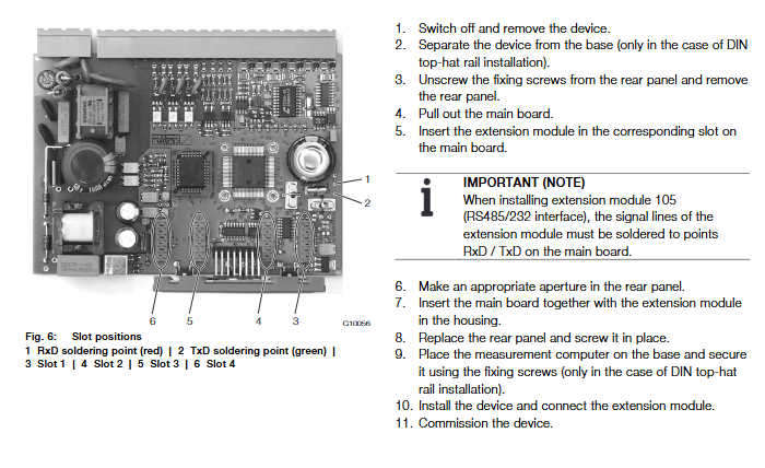
Expansion module installation: power-off operation, the internal capacitor of the device remains charged even after power failure; ESD anti-static measures must be taken during operation; Disassembly and assembly will damage the calibration seal.
4 slots on the motherboard; Slot 1-3 is fixed for 12 channels of infrared sensor input; Slot 4 is used for option module (only one can be installed, and one of two can be selected: analog output module/RS232 ‑ RS485 Modbus communication module).
Terminal definition: 12 channel infrared sensor input terminal; Pt100 environmental temperature input; Two alarm outputs and one equipment fault output; M-Bus bus; 24VDC power supply.
Infrared sensor wiring: 4-core cable, green wire must be insulated when idle; Probe output impedance ≥ 10k Ω.
Operation
Pre power on inspection items: mechanical installation in place, all wiring correct, and power supply voltage matching nameplate. Power on operation steps:
Connect the 24VDC power supply, and the LCD will display the startup interface;
Enter the menu to set the system date and time (data log timestamp depends on the clock);
Select the desired main display screen (maximum value, physical quantity, electrical quantity, etc.).
Equipment operation
Key navigation: up arrow (increase/flip up), down arrow (decrease/flip down), confirm/return button; The toolbar icon at the top of the LCD displays status such as running, error, and writing to EEPROM.
Parameter modification: Only a small number of basic parameters (time, password, bus address) can be modified locally on the panel; The vast majority of parameters require the setting of FCOM200 (ParaTool) parameter software on the PC end.
Level 3 access security level
S1: Factory/Maintenance Level;
S3: Password lock, customer parameters can be modified after entering the password;
S4: Fully open, all parameters can be read and written.
Configuration and parameterization
Complete menu tree: Start menu, maximum temperature Tmx, physical quantity, electrical quantity, error message, date and time, service, data logger, printing tool, measuring point label, device data, password.
Main menu description
Tmx maximum temperature: displays the current highest temperature of infrared measuring points 1-12;
Physical values: real-time temperature of each measuring point, Pt100 temperature of the environment, and identification of measuring points;
Electrical values: Pt100 resistance temperature, input and output electrical signals of expansion module;
Error messages: Save the last 10 power on/off records and 10 process fault records with timestamps; Clear process alarms; The internal error of the device is a 4-digit binary encoding;
Date/Time: Run hour count, set system clock;
Service menu: security level status, display screen testing, LCD contrast, various counter reset, software and hardware version viewing;
Data logger: circular buffer (up to 200 records, overwrite the oldest when full); Configurable recording period of 1 hour to 3 months, with an integration period starting from 15 minutes; Store the temperature, maximum/minimum/average value, and ambient temperature of each measuring point, with a timestamp attached;
Print tool: Output all measurement data to the HP82240B infrared printer through the front infrared optical interface of the device;
Tag name measurement point tag: measurement point name, can only be edited by PC software;
Device Data: Serial number, M-Bus address baud rate, protocol, language, log cycle, identification of installed extension modules;
Password: 4-digit password management permission.
PC configuration software FCOM200 (ParaTool)
Two connection methods: ① Infrared optical head on the front of the device; ② M-Bus bus adapter; The PC and device bus parameters (address, baud rate) must match.
Error message
Process errors: Pt100 out of range; The global maximum temperature exceeds the upper limit; The temperature of any infrared measuring point 1-12 exceeds the range; The LCD “Error” icon flashes to indicate.
Device error: 4-bit binary encoding for internal device faults, code addition for multiple faults;
0000 has no faults; 0001 configuration error; Unit 0002 configuration error; 0004 display parameter error; 0100-0800 respectively represent faults in expansion modules 1-4.
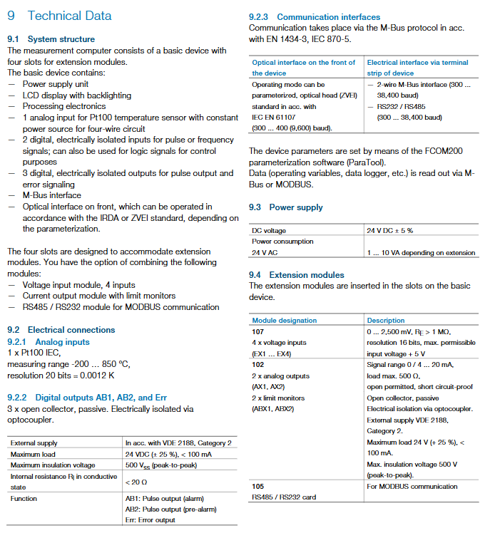
Technical data
Host hardware architecture: 4 expansion slots on the motherboard; Equipped with backlight LCD; Pt100 four wire input; 3-channel isolated collector open circuit digital output (pre alarm, main alarm, equipment fault Err); M‑Bus; Front panel infrared optical interface IRDA/ZVEI.
Expansion module selection
Module 107: 4-channel voltage input;
102 module: 2-channel 4-20mA analog output+2-channel limit monitoring;
105 module: RS232/RS485 for Modbus.
Electrical Specifications
Pt100 input with 20 bit high resolution;
Digital output: open collector, maximum 24VDC,<100mA;
Communication: M-Bus; Optional RS232/485 Modbus; Infrared spectroscopy mouth;
Power supply: 24VDC ± 5%, power consumption 1-10VA varies with the expansion module.
environmental conditions
Host operation -5 ℃~55 ℃; Storage -25-70 ℃; Allow condensation;
Vibration impact meets IEC standards; EMC electromagnetic compatibility meets the strong electromagnetic environment requirements of switchgear such as EN50082-2.
CS infrared probe parameters: IP65; Optics 15:1; Reproducibility of temperature measurement ± 0.75 ℃ or ± 0.75% reading.
Mechanical dimensions
Panel installation opening 139mm × 69mm;
It also supports DIN rail and wall mounted installation.
Maintenance and repair
Replace fuse: 0.8A; power must be cut off and the machine must be disassembled, which will damage the calibration seal and prevent static electricity during operation;
Infrared probe cleaning: Do not use solvent based cleaning agents; Compressed air blows floating dust; Wipe the lens with a soft damp cloth/water-based glass cleaner.