ABB SUE 3000 High Speed Power Switching Device Operating Instructions
Overall description and safety requirements
Applicable personnel: Electrical engineers must have received professional training, and non professionals are not allowed to install and debug; The equipment is only suitable for indoor installation and complies with VDE and IEC related specifications.
Copyright Disclaimer: Reproduction of documents is prohibited without written permission from ABB; The manufacturer is not responsible for damages caused by incorrect operations, and original spare parts must be used for repairs.
Abbreviation definitions: CT current transformer, DSP digital signal processor, FUPLA functional block programming language, RHMI remote human-machine unit, LON, SPABUS, Modbus RTU, etc.
Typical two modes of primary wiring
Mode 1: Two feeder circuit breakers, single busbar, one in use and one backup; Quickly switch the load to the backup feeder in case of a malfunction.
Mode 2: Two feeders are connected with a three switch busbar circuit breaker, and the busbar realizes the mutual switching of two sections of busbars.
Precondition for operation: The two feeders should be as independent as possible; Need to collect two feeder lines, bus voltage, and feeder current; Collect auxiliary contact position signals of circuit breakers.
Hardware structure
Central unit (host): including CPU main control board, DSP digital signal processing board, power supply, multiple binary I/O boards, analog input board; Optional communication board and analog output board.
DSP is responsible for analog acquisition, phase angle/frequency calculation; MCU is responsible for logic control and communication; Internal CAN bus completes board data exchange.
There are two hardware versions of binary I/O: mechanical relay output version and solid-state static relay version.
HMI human-machine unit (RHMI): an independent cabinet door installation unit with built-in auxiliary power supply; Through RS485 shielded twisted pair cable and host communication, the maximum cable length is 100m.
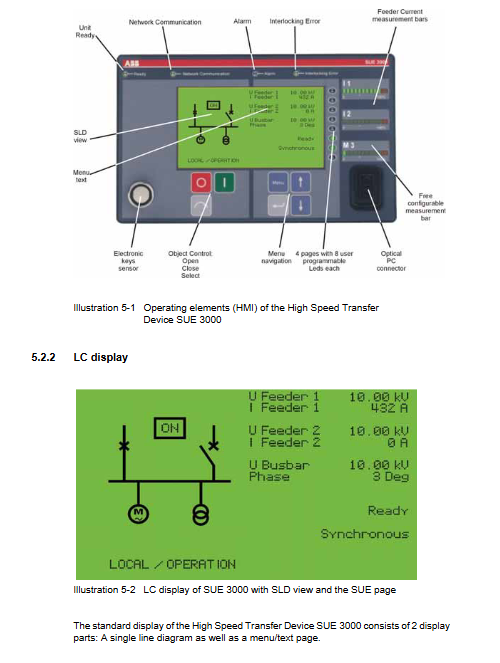
Hardware composition: backlit LCD display screen, operation buttons, three color programmable LED, three analog LED light columns, optical RS232 debugging port, electronic key sensor.
The LCD is divided into two areas: the left single line diagram SLD and the right text data/menu.
4 system status LEDs: Ready for Heady device, Network Communication, Alarm alarm, Interlocking Error interlock fault.
Electronic keys are divided into two categories: control keys (local/remote/disable control), protection parameter setting keys (SET/OPERATIVE), and permission isolation to prevent incorrect setting values.
Working principle, interface and switching mode
3.1 External Interface
Circuit breaker interface: Take the NO/NC passive auxiliary contact of the circuit breaker for position determination; Perform XOR logic verification, devices with inconsistent positions report faults and switching is prohibited; Monitor the energy storage of the circuit breaker spring and the working position of the handcart; Output opening and closing control commands; Coil disconnection monitoring, control circuit fault directly set to “Not Ready” to prohibit switching.
Analog measurement input: two-way feeder voltage, bus voltage, feeder current; DSP continuously calculates phase angle difference, frequency difference, and voltage amplitude to determine in real-time whether fast switching conditions are met.
Switching startup modes (3 types, different priorities) 1) Protection startup: external protection contact, direction locking, high priority, used for feeder fault tripping linkage switching; 2) Undervoltage startup: The device detects bus undervoltage internally, or an external undervoltage relay contact is connected; 3) Manual start: HMI local or remote input, with the lowest priority.
Remote control and remote signaling
Remote signaling: All states are output through passive contacts, including ready/not ready, various switching completion signals, fault alarms, and load shedding signals.
Remote control: Open the contact to realize device switching, manual switching, and reset locking; Remote control pulse ≥ 100ms.
3.2 Upper communication (choose one communication board from three, hardware mutually exclusive)
SPABUS (ABB Private Bus): master-slave polling, supports fiber optic, ring/star topology.
LON (LAG1.4): ABB substation automation standard bus, supporting horizontal device GOOSE network variables, connected to MicroSCADA Pro; Supports high-precision time synchronization with VATS (1ms) and regular network time synchronization (10ms).
Modbus RTU: RS485/fiber optic interface; Support event caching and fault recording in COMTRADE format for uploading.
3.3 Four automatic switching modes (the device automatically selects based on voltage phase frequency conditions)
Determine 4 thresholds for fast switching (factory default): phase angle ± 20 °; Frequency difference<1Hz; Backup power supply>80% Un; Bus voltage>70% Un.
Fast Transfer quickly switches between two power sources when the synchronization conditions are met, and simultaneously issues opening and closing commands. Can set a command offset of 0-30ms to compensate for the time difference between the opening and closing of the circuit breaker; There may be brief no current gaps or brief parallel connections.
The Prime Minister of the 1st phase coincidence switch is not synchronized. First, disconnect the working power supply, predict the zero crossing of the voltage difference, and close the backup power supply at the moment of minimum voltage difference; Require the total operating time of the circuit breaker to be less than 100ms, and the maximum frequency slip of the busbar to be 15Hz/s.
Residual voltage dependent residual voltage switching trips the working power supply, and when the residual voltage of the busbar decays to the set value (default 40% Un), the backup power supply is closed without considering the phase angle.
Time delayed switching to backup safety mode; When measuring PT faults and unable to obtain bus voltage, the backup power supply is turned on after a fixed delay (default 2 seconds).
Additional features
Decoupling protection: During fast switching, if the circuit breaker to be disconnected refuses to open and the two power sources are connected in parallel for more than the set time (default 100ms), the backup switch that was just closed will immediately trip again; The device locking requires manual reset.
Load shedding output: Output contacts during non fast switching, jump secondary loads, and prepare for restarting motor equipment.
External interlocking input: overcurrent lockout switching, PT small switch position monitoring, allowing/prohibiting directional switching, prohibiting residual voltage/delay switching, etc.
HMI local operation and menu system
HMI has two sets of key permissions, with different permissions restricting menu read and write.
Main menu page
SUE Overview Page: Single line diagram SLD, displaying the voltage and current, phase angle, synchronization status, and device ready status of each feeder.
Commands command page: Device on/off, manually triggered switch.
E-Key Status: Electronic key status: Set control mode (local/remote/local+remote/disable control); Protection mode SET (adjustable setting)/OPERATIVE (operation prohibited from changing setting).
Alarm page: Up to 4 pages of alarms, can be latched, and needs to be reset and cleared.
Measurements page: real-time measurements such as frequency, frequency offset, and operating hours.
Reset page: Reset alarm, maximum quantity, electrical degree, circuit breaker count, fault recording, event counter; Partial reset requires SET protection key.
Events page: Save up to 50 switching events with timestamps and loop coverage.
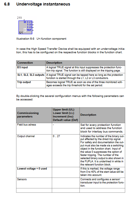
Protection page: View/modify parameters such as undervoltage protection; Parameters can be permanently saved, temporarily saved, or abandoned for modification.
Control page: Various control parameters such as switching time and direction enable.
Service page: firmware version, communication address, LCD contrast, system clock, FUPLA cycle statistics.
Test page: LCD, LED, button self-test; One time equipment testing mode (will shield interlocking and risky operations).
Front panel optical port: Connect the laptop to an optical RS232 cable to enable configuration download and reading of recorded data.
PC configuration software (SUE3000CONF)
5.1 Software Environment
Run Windows 2000; After installation, English/German/Italian/Czech languages can be selected; The project suffix is. UE, along with accompanying files such as bak, wir, lst, etc.
5.2 Core Function: FUPLA Graphic Function Block Programming
Drag and drop function blocks, connect to build logic; The application cycle must be ≤ 15ms, otherwise the device cannot operate reliably.
HSTD core functional block: includes all digital inputs, digital outputs, and all switching parameter setting windows (general, circuit breaker, control, monitoring, time, analog, event, pin).
Configurable: circuit breaker opening and closing command offset, decoupling delay, phase angle threshold, frequency threshold, residual voltage threshold, load shedding delay, and enable switching modes in all directions.
Fault Recorder
Up to 7 analog signals and 32 digital switch signals can be recorded; Sampling rate of 1.2kHz; 100-2000ms before the fault, up to 4900ms after the fault; cyclic caching; Export to COMTRADE format and analyze the recorded waveform using WINEVE/REVAL software.
Software operation: Project creation/saving; Configure download to device (device stops working during download); Upload configuration from the device; Export input/output status and measurement values; Collect data continuously and save it as text.
The software automatically verifies the project before downloading, including I/O resources, DSP load, number of connections, cycle time, etc.
Installation, wiring, commissioning, and maintenance
Installation and wiring: Install the host in the control cabinet; Installation of HMI cabinet door openings; Analog signals and communication must shield cables; The system is fully protected by grounding and meets EMC anti-interference requirements.
Wiring checklist: CT circuit, PT circuit, auxiliary power supply, trip circuit, binary input circuit; Check the auxiliary contacts of the circuit breaker.
Operation is divided into two steps
Cold debugging (without primary high voltage): all logic, interlocking, and switching timing tests;
Hot commissioning (with actual load): Live actual switching test.
Maintenance: The manual provides a list of spare parts; Maintenance precautions for distinguishing between mechanical relay I/O versions and solid-state I/O versions.
Alarm, event, technical data
Alarm events: Ready/Not Ready, phase angle exceeding limit, frequency difference exceeding limit, backup power loss, abnormal bus voltage, control circuit failure, decoupling action, various switching completion events.
Hardware Technical Parameters
Power supply: 48-220VDC;
I/O: Analog input 16 bit AD; Binary output divided into mechanical relay/solid-state;
Environmental temperature; EMC meets industrial and substation standards;
Communication: Choose one of SPABUS/LON/Modbus RTU.