ABB REL670 (Relion 670 series) line distance protection device
Analog inputs
There are multiple hardware versions of the TRM transformer input module: TRM12I, TRM6I6U, TRM7I5U, TRM9I3U, corresponding to different numbers of current and voltage channels.
The reference phase angle channel PhaseAnglesRef can be set as the phase calculation reference.
Must enter: CT primary and secondary current, VT primary and secondary voltage, CT star point polarity.
Dual channel AD sampling architecture: ADx_Low low gain, ADx_Hi high gain, expands dynamic range, and dual channel sampling mutual verification, with AD abnormal output alarm.
Local HMI (Human Machine Interface)
Provide two types of panel hardware: small-sized text HMI and medium-sized graphic HMI.
Hardware composition
LCD display screen: Medium sized graphics screen supports drawing editable single line diagrams (SLD), up to 12 pages of single line diagrams; The small screen only supports text display.
Keys: on-off I/O keys, menu, confirm E, cancel C, directional navigation, reset, local remote L/R key switch; Front panel isolation RJ45 debugging network port.
LED indicator light
Top 3 status LEDs (Ready, Start, Trip);
There are 15 programmable alarm LEDs on the right, 6 red trip indicators, and 9 yellow start/alarm indicators.
LED working modes (6 sequences)
Followe-S/Followe-F: Follow the input signal, constantly on/flashing;
LatchedAck: Locked, requires manual confirmation of reset;
LatchedColl: Collection mode, cumulative storage of multiple faults;
LatchedReset-S disturbance automatic reset mode: New faults automatically clear the previous disturbance alarm; Configurable disturbance determination time tRestart and maximum signal duration tMax.
HMI configurable items: language, backlight timeout, contrast, event sorting (latest priority/oldest priority), IEC/ANSI symbol font.
Basic public functions of IED (universal across the entire 670 series)
4.1 User Authorization
Multi role permission model: Guest Guest, SystemOperator, ProtectionEngineer, DesignEngineer, SuperUser, UserAdministrator.
Permission differentiation: read-only, basic settings, advanced protection settings, application logic configuration, FTP file transfer, user account management.
User accounts can only be created and downloaded to devices on PCM600; Local HMI only performs login and logout; Automatically return to visitor read-only mode upon timeout; The password has a maximum of 18 characters.
4.2 Whole machine self-monitoring Self supervision
Continuous monitoring: watchdog, AD sampling, IO board, communication, clock, file system, runtime engine.
Output two types of total signals: FAIL serious fault and Warning; Hardware output passive contact INTERNAL FAIL.
Internal event list, cyclically storing 40 fault records; Includes IO faults, LON/SPA/IEC61850 communication faults, clock faults, and setting change alarms.
4.3 Time Synchronization
The device is divided into two clock systems: software clock (event marking) and hardware clock (differential protection, AD sampling).
Support synchronization sources: SNTP, IRIG-B (optical/electrical), GPS, PPS second pulse LON、SPA、 Binary pulse division.
Event time scale resolution of 1ms; RTC capacitor backup power-off maintains clock for up to 5 days.
Support daylight saving time (DST) settings; IEDs can be configured as SNTP time servers.
The IEC61850-9-2LE process bus must be equipped with a hardware synchronization source (IRIG-B/PPS).
4.4 Parameter Setting Groups
Up to 6 independent fixed value groups; Activation groups can be switched through HMI, remote backend, and binary input hard contacts;
Activate multiple groups simultaneously, with priority given to groups with lower numbers; Switch the fixed value output pulse signal SETCHGD.
4.5 ChangeLock Change Lock
After debugging is completed and enabled: it is prohibited to modify configuration and protection settings; Still allow monitoring, event reading, waveform recording, control operations, and switching of fixed value groups. You can choose to lock the HMI, lock the communication port, or both simultaneously, controlled by binary input hard contacts.
4.6 TestMode Test Mode
By default, all protection functions are blocked when entering testing mode; Can be individually unblocked for single function verification;
In testing mode, you can choose to prohibit events from being uploaded to the backend to avoid contaminating the SCADA database with a large number of testing events;
Support external hard contact triggering to enter testing mode, compatible with RTXP testing terminals.
4.7 Signal Matrix Tool SMT
Binary input SMBI, binary output SMBO, mA analog input SMMI, analog input SMAI; Realize free mapping between hardware IO and internal logic signals.
Complete set of protection function modules
5.1 Differential Protection
HZPDIF single-phase differential (high impedance differential): used for applications such as busbars, based on the high impedance principle, to resist CT saturation, providing logic blocks, input and output, and setting parameters.
5.2 Impedance (Distance) Protection [REL670 Core Function]
Supports two types of impedance characteristics: quadrilateral and Mho; Provide dedicated distance components specifically for series compensation lines.
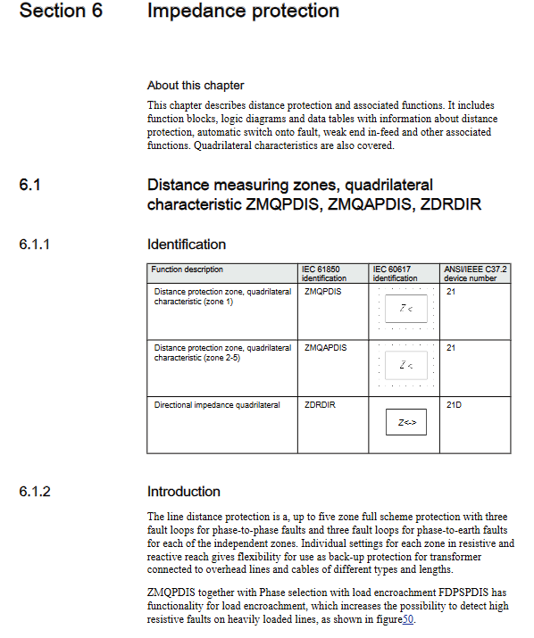
Quadrilateral distance element ZMQPDIS: multiple distances between phases and grounding; Load suppression, minimum operating current, phase selection logic;
ZMCPDIS for series compensation lines: specifically designed to solve impedance reversal caused by series compensation capacitors, with a special direction determination algorithm;
Mho circular characteristic ZMHPDIS;
Phase selection components: FDPSPDIS fixed angle phase selection, FRPSPDIS adjustable angle phase selection; Identify phase to phase faults, ground faults, and three-phase faults, with load intrusion suppression capabilities.
Power swing detection ZMRPSB and power swing logic ZMRPSL: distinguish between real faults and system oscillations; During oscillation, distance protection can be locked or specific segments can be opened;
Extreme slip protection PSPPPM; Combined with fault ZCVPSOF; Priority logic PPLPHIZ.
5.3 Current protection
Includes complete overcurrent backup protection, can be used independently, and also serves as a backup for distance protection:
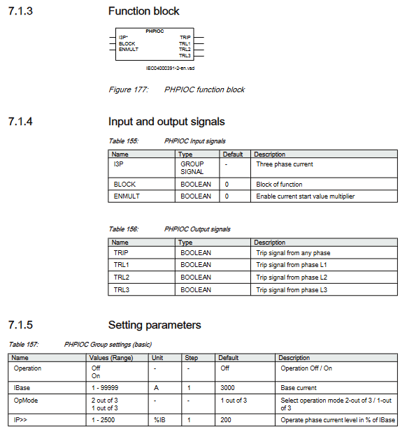
Instantaneous phase overcurrent PHPIOC; 4-stage overcurrent OC4PTOC, supporting second harmonic excitation inrush current blocking;
Instantaneous residual grounding overcurrent EFPIOC; 4-section grounding overcurrent EF4PTOC (supports internal/external polarization);
4-stage negative sequence overcurrent NS4PTOC; Sensitive direction grounding SDEPSDE;
Thermal overload LPTTR; Circuit breaker failure protection CCRBRF; Short lead protection STBPTOC; Extremely inconsistent protection CCRPLD;
Direction over power, direction under power, and disconnection detection BRCPTOC.
5.4 Voltage Protection
Undervoltage UV2PTUV in two-phase section and overvoltage OV2PTOV in two-phase section; Remaining overvoltage ROV2PTOV; Overexcitation protection OEXPVPH; Voltage differential VDCPTOV; Loss of voltage detection LOVPTUV.
5.5 Frequency protection
Underfrequency SAPTUF; Overfrequency SAPTOF; Frequency slip df/dt SAPFRC, used for low-frequency load shedding scenarios.
5.6 Multi functional universal protection CVGAPC
12 sets of universal current and voltage protection, customizable criteria, and implementation of various special logics.
5.7 Secondary System Supervision
CCSRDIF CT current circuit monitoring, detecting CT disconnection;
SDDRUFF PT fuse failure monitoring, using negative sequence and delta voltage delta current algorithm to identify PT faults and lock voltage related protection.
Control Function Control
Check synchronization/no voltage SESRSYN: Determine the synchronization conditions for closing, and adjust the voltage, phase angle, and frequency conditions;
Automatic reclosing SMBRREC: Multiple reclosing, supporting time series logic for different fault types;
Interval control APC, Bay control QCBAY; Switch controller SCSWI; Circuit breaker SXCBR and isolation switch SXSWI logic nodes, following IEC61850;
Complete interlocking logic library: predefined interlocking logic diagrams for bus tie, bus isolation switch, 1/2 circuit breaker wiring, double circuit breaker interval, line interval, and transformer interval; Support hard contact interlocking+GOOSE network interlocking.
Scheme communication for longitudinal/channel communication logic (critical for line protection)
Implement longitudinal protection logic for distance and grounding protection:
ZCPSCH universal longitudinal logic: allows for under range, over range, locking, unlocking, and direct tripping Intertrip;
ZC1PPSCH phase separated longitudinal coupling;
Current reversal logic ZCRWPSCH, weak feed WEI logic: solves the problem of current reversal in loop network and double ended power supply faults, and weak power supply side protection;
Local acceleration logic ZCLCPLAL; Ground fault longitudinal ECPSCH; Grounding current reversal and weak feedback ECRWPSCH.
Custom Logic Function Block Library
Provide a large number of freely configurable basic logic units, allowing users to build custom logic: Boolean: AND, OR, NOT inverting INV, XOR XOR; Timer: regular TIMER, pulse timer PULSETIMER, adjustable TIMERSET; SR-MEMORY reset memory; LOOPDELAY circuit delay; Data conversion: 16 bit Boolean to integer B16I; Convert integers to Boolean IB16, etc.
Monitoring, waveform recording, fault location monitoring
Measurement quantities: three-phase current and voltage, sequence components, active and reactive power, power factor;
Fault location LMBRFLO: impedance algorithm calculates the distance of the fault point and supports compensated/uncompensated line models;
Event list and disturbance report; COMTRADE format fault recording; Trip value record; Counter; Event counter.
Measurement Meter
Pulse counting PCGGIO; Electric energy and demand calculation ETPMMTR module.
Communication System Station&Remote Communication
IEC61850-8-1 Station Bus: MMS, GOOSE; Support GOOSE receiving and sending to achieve inter compartment interlocking;
IEC61850-9-2LE process bus receives MU samples;
Traditional protocols: IEC60870-5-103, LON, SPA bus;
Hardware communication board: OEM optical Ethernet, SLM serial port LON board, GTM GPS timing board, LDCM line differential communication board;
Support PRP/HSR network redundancy.
Hardware module Hardware
REL670 modular plug-in architecture, main boards:
CBM/UBM backplane; NUM digital processing CPU board; PSM power module;
TRM transformer input board; ADM analog-to-digital conversion with synchronization;
BIM binary input; BOM solid-state output; IOM hybrid IO; MIM milliampere analog input;
Communication board SLM, OEM optical network port, LDCM line communication, GTM-GPS clock, IRIG-B timing board.
Installation method: 19 inch rack, panel embedded, wall mounted; Multiple chassis sizes.
The complete terminal wiring diagram and mechanical dimension drawing are located in the latter half of the manual.