ABB REM543/REM545 motor/generator protection and measurement device
Overall characteristics of the product
Input compatible with two collection methods
Conventional: CT (1A/5A), PT voltage transformer;
Sensor mode: Roche coil current sensor, voltage divider, connected through BNC shielded coaxial cable.
Human machine interface: two solutions – local fixed graphic LCD HMI; External independent display panel (powered separately, suitable for cabinet door split installation). The panel supports dynamic simulation MIMIC, programmable LED alarm, and local on/off operation.
Built in IEC61131-3 standard PLC function library, which can achieve interval interlocking and timing logic, and rely on LON bus to achieve logical interaction between devices, reducing hard wiring.
Recording capability: transient disturbance recording (up to 16 analog signals+16 digital signals), event recording, circuit breaker operation counting.
Optional RTD/mA module: collects stator, bearing, and ambient temperature; Provide 4 channels of 0-20mA analog outputs to interface with the dashboard and external PLC.
Communication interfaces: SPA bus, LON bus Modbus‑RTU; Front panel optical RS232 debugging port.
Application scenarios: diesel generators, hydro generators, steam turbine generators; High power high-voltage asynchronous/synchronous motor; Ship crew; Plant power generator transformer unit protection.
Hardware I/O architecture
Hardware version differentiation
Suffix A: No sensor input, only connected to regular CT/VT;
Suffix B: with sensor channel, supporting Roche coil and voltage divider;
Power supply module PS1: Two power supply options: AC110-240V/DC24-60V/DC110-220V.
I/O difference
Model number input power output (trip control) signal output
REM543 15:00 5-way bipolar power output 5-way NO/NC signal output
REM545 25 o’clock 9-way bipolar power output, 5-way NO/NC signal output
Optional RTD module: 8-channel RTD/DC analog input; 4-channel isolated 0-20mA analog output. The output is divided into three categories:
HSPO high-speed power output: used for circuit breaker tripping and closing;
PO power output: switch device control;
SO signal output: alarm, status signal, unable to drive circuit breaker coil.
Terminals and Machinery
Chassis: 1/2 19 inch rack, 6U height; Weighing approximately 8kg;
Protection: front panel IP54, rear terminal IP20;
Electromagnetic compatibility: meets the IEC60255 series, vibration, impact, and earthquake tests; Insulation withstand voltage of 2kV, impulse withstand voltage of 5kV.
Complete protection function (distinguishing between motor M mode/generator G mode)
The device has two functional levels: Motor motor mode and Generator generator mode. Different protection modules are enabled, and each functional block has a corresponding ANSI equipment number.
🔹 short circuit protection
Three phase non directional overcurrent (51/50): low section, high section, instantaneous; Support multiple inverse time curves.
Directional overcurrent (67): Generator mode is available.
Differential protection (87M/87G)
Diff3: High impedance/flux balanced differential, universal for motors and generators;
Diff6G: Stable three-phase differential, specifically designed for generators.
🔹 Ground fault protection
Non directional grounding overcurrent (51N/50N) low/high/instantaneous;
Directional grounding fault protection (67N);
High impedance limited grounding REF1A (87N, generator);
Remaining overvoltage protection of 59N.
🔹 Overload and unbalance protection
TOL3Dev (49) thermal overload: motor/generator/transformer thermal model, supporting stator and rotor time constants, restart lockout;
Negative sequence overcurrent protection NPS3 (46) reflects three-phase imbalance and phase failure.
🔹 Voltage protection
Overvoltage 59, undervoltage 27, phase sequence voltage protection.
🔹 Frequency protection (generator mode)
Over frequency, under frequency, df/dt frequency slip, up to 5 segments, used for low-frequency load shedding.
🔹 Generator specific protection
Underexcitation protection UE6 (40);
Overexcitation protection OE1 (24) U/f protection;
Reverse power/low power protection UPOW6 (32);
Directional over power OPOW6.
🔹 Motor specific protection
Motor start monitoring MotStart (48/14/66): Monitor start time, locked rotor, allowed start times, restart after start prohibited;
Undercurrent protection NUC3 (37);
Reverse phase protection PREV3 (46R).
🔹 Public Additional Protection and Surveillance
Circuit breaker failure protection CBFP (62BF);
Excitation inrush current detection Inrush 3 (68);
PT fuse failure monitoring FuseFail (60);
Check the same period/no pressure SCVC (25), and connect the generator to the grid for use.
Control and status monitoring functions
Device Control
Up to 2 circuit breakers, 5 isolating switches, and 2 three state isolating switches;
Local/remote control; Complete interval interlocking logic;
The HMI panel allows direct operation of switches.
Equipment status monitoring Condition monitoring
Trip circuit monitoring TCS, detecting disconnection in the tripping and closing circuit;
Circuit breaker electrical wear counting and operation time statistics;
Circuit breaker spring energy storage, SF6 gas pressure monitoring;
Plan maintenance alerts.
Measurement function
Three phase current and voltage, zero sequence quantity, active and reactive power, power factor, bidirectional electrical energy, frequency; External RTD is used to measure the temperature of windings and bearings.
Wave recording
MEDREC16 disturbance recording: up to 16 analog+16 digital channels;
Event SOE record; Run statistical counters.
Software tools and configuration methods
CAP505: Main engineering software, completes protection setting, I/O mapping, and IEC61131-3 PLC logic programming;
Relay Mimic Editor: Edit HMI local dynamic simulation MIMIC screen;
CAP501: Fixed value tool;
LNT505: LON bus network configuration tool;
Debugging interface: Connect the optical RS232 port on the front panel of the device to a computer;
Support switching between multiple fixed value groups and remote modification of fixed values.
PLC programmable logic
Complete functional block library: AND/OR/NOT, timer, pulse timer, RS trigger, comparator, data type conversion, can achieve custom interlocking, alarm, timing; Realize signal exchange between multiple devices through LON bus, reducing secondary hard wiring.
Communication capability
SPA bus: ABB’s old internal bus;
LON bus: focus on achieving peer-to-peer communication between devices and cross interval interlocking logic;
Modbus RTU (supported by REM543);
Hardware interface: Front panel optical RS-232; Backboard X3.2 (SPA/Modbus); X3.3(SPA/LON); Support fiber optic modules RER103 and RER123 for fiber optic isolation.
Note: The REM54 series does not support IEC61850 or the HART protocol, and cannot be used with DHH805-A handheld devices; Debugging relies on CAP505 software and local HMI.
Order coding rules
Order number example: REM543CM212AAAA Segment meaning:
Model: REM543/REM545;
Functional level: M=motor mode, G=generator mode;
Hardware version number;
Power type;
A/B: A=Normal CT/PT; B=Supports Roche sensors;
Display screen: A fixed local HMI, B external independent display panel.
Typical application wiring example
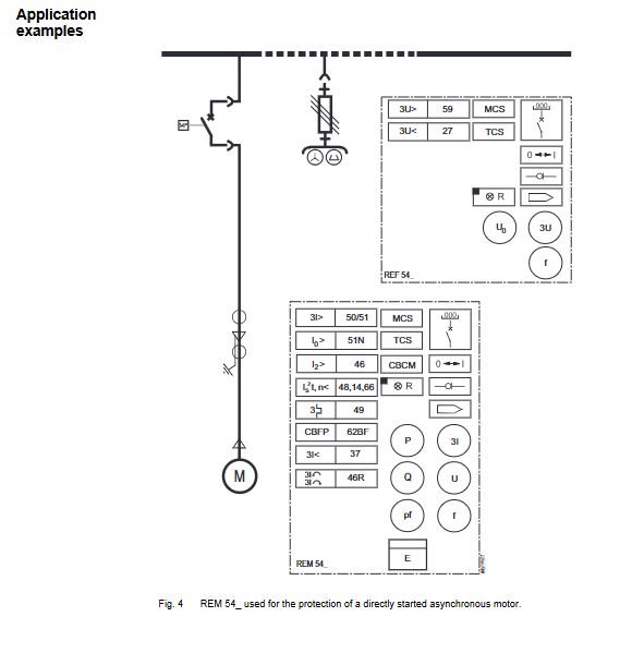
Directly start asynchronous motor protection;
Starting synchronous motor with autotransformer;
Diesel generator single machine grounding system;
Generator transformer unit protection;
Multiple units in the power plant are connected to the grid for protection.
Key points of technical data
Auxiliary power supply: AC 110-240V, DC24-2220V; Power consumption<50W;
The digital input threshold can be configured; The maximum output contact is 250V AC/DC;
RTD supports Pt100, Pt1000, Ni, Cu copper resistors;
Environment: Working -10 ℃~+55 ℃, Storage -40~+70 ℃;
Event recording and waveform recording will not be lost in case of power failure.