ABB AO2000-LS25 laser gas analyzer
Measurement principle and overview of the whole machine
TDLAS tunable diode laser absorption spectroscopy technology: The laser scans the characteristic absorption spectral lines of the target gas, uses wavelength modulation, extracts the second harmonic signal, and calculates the gas concentration; Compensate for the spectral line broadening effects caused by pressure and temperature.
Only measuring free gaseous molecules does not respond to substances adsorbed in dust or droplets. When comparing data with an extraction analyzer, attention should be paid to deviations.
Laser safety level: Oxygen measurement is classified as 1M class; The remaining tested gases are classified as Class 1, and the laser is invisible infrared light. It is prohibited to open the casing while powered on, and optical instruments are prohibited from directly viewing the beam.
Hardware composition
Launching unit TU: equipped with temperature controlled diode laser, collimating optics, main control CPU, LCD local display screen;
Receiving unit RU: focusing lens, photodetector, receiving signal processing board;
Power supply unit: AC100-240V input, DC18-36V output to supply TU;
Blowing air path: flange blowing, optional TU/RU body blowing, protecting optical windows from dust pollution.
Applicable range of optical path: 0.5-6m; flange standard DN50-PN10.
Communication interface: RS-232 isolated serial port, RJ45 Ethernet; Analog input supports multiple 4-20mA (temperature, pressure, flow external sensors).
Preparation before installation
2.1 Requirements for measuring point location
The upstream section of the pipeline is a straight pipe with a diameter of ≥ 5 times the pipe diameter, and the downstream section is a straight pipe with a diameter of ≥ 2 times the pipe diameter; Avoid eddy currents and dead zones.
Installation and operation space: At least 1000mm outward from the receiving side, with a maintenance space of ≥ 500mm up and down.
2.2 Flange Opening and Installation Tolerance
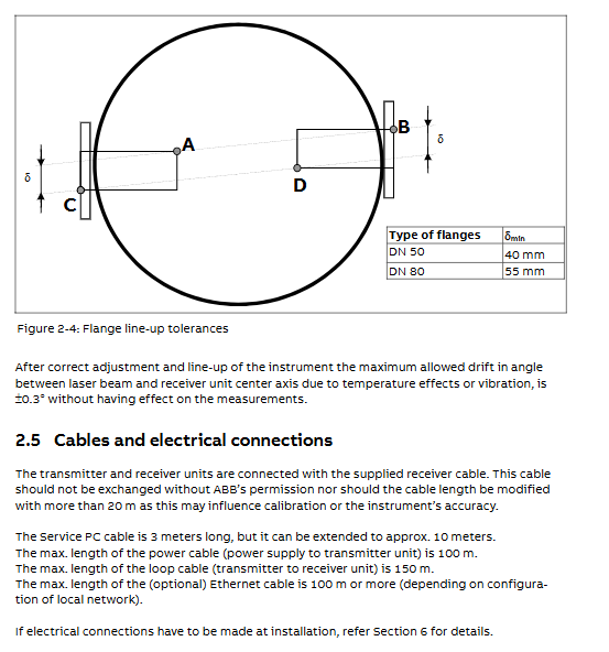
The flanges on both sides of the pipeline must be installed facing each other; The perpendicularity tolerance between the flange end face and the centerline of the pipeline is ± 1.5 °; The center deviation of the flange meets the minimum requirement of DN50 δ=40mm.
Optional shut-off valve flange for continuous process disassembly and maintenance; High risk/corrosive working conditions require isolation flanges.
2.3 Cable specifications and maximum length
Maximum allowable length for cable type
TU-RU receiving communication cable 150m
The power cable from the power supply unit to the transmission unit is 100 meters long
PC debugging RS-232 cable 10 m
Ethernet LAN cable 100 m
Without ABB’s permission, it is not allowed to change the cable length without authorization, as it may alter the calibration accuracy.
2.4 Requirements for blowing air source
Flange blowing (protective window): instrument compressed air, ISO8573‑1 Class2‑3; Typical flow rate 20-50L/min; The initial velocity of the experience value blowing airflow is taken as 1/10 of the process gas flow rate in the pipeline. Partial operating conditions such as oxygen measurement require nitrogen purging.
TU/RU body blowing (optional): High purity nitrogen gas must be used with a flow rate of less than 0.5L/min to prevent oil-water contamination of internal components.
On site installation, alignment, and power on operation
The complete operation manual provides a concise checklist.
Fix the blowing adjusting unit to the DN50 flanges on both sides of the pipeline; Apply lubricating grease to all threads; Tighten the M16 bolt and tighten the O-ring.
Connect the blowing pipeline and start blowing air first.
Install the window adapter ring and install the O-ring; Install the transmitting and receiving hosts separately.
Wiring: TU-RU signal cable, external 4-20mA temperature and pressure probe, power supply unit power supply.
Power on: The power supply unit outputs DC18-36V to the TU, and the equipment enters the startup self-test; After about 3-5 minutes of complete startup, the laser temperature control is stable.
When the LCD is just powered on, it usually reports Laser line up error and Low transmission, which are normal and indicate that the beam is not aligned.
Coarse alignment: Red laser alignment fixture
Install red light calibration fixtures on the transmitting and receiving sides respectively; Adjust the M16 flange adjusting bolt, align the red light spot with the center of the opposite device opening, and tighten the positioning screw.
Fine tuning of light (voltage method) using a battery type floating multimeter, connected to the device’s alignment test socket; Adjust the screws on both sides to maximize the alignment voltage (typical -3V corresponds to 100% transparency); Repeatedly iterate the sending and receiving ends, and tighten the screws.
The target transmittance for clean working conditions is 90-100%.
PC debugging connection: RS-232 (9600, 8N1) or Ethernet; Default IP: 192.168.1.237, port 5001.
PC Service Software
The software runs on the Windows platform without installation, and can be run directly; Divided into user mode (daily debugging, restricted permissions), advanced mode (password, all parameters, calibration), supporting Demo mode.
Main menu functions
Measurement menu: Real time display of all real-time variables such as instantaneous concentration, average concentration, transmittance, second harmonic amplitude, laser temperature, gas temperature and pressure, internal device temperature, etc.
Plot readings: concentration and transmittance time series curves.
Second harmonic signal: View absorption spectrum waveforms, a core tool for fault diagnosis, and can save waveform files.
Log reading data recording: Record data according to a custom cycle and output ASCII log files.
View error log: Read and clear fault logs and system logs, and send fault analysis to ABB technical support.
Measurement configuration (most important)
Gas pressure and temperature source: fixed value/4-20mA external probe/internal sensor; The pressure unit must be bar absolute pressure; Support conversion of temperature and pressure units.
Optical path parameters: gas path length, flange path length, TU/RU internal path length (factory preset, not recommended for modification).
Concentration averaging filtering, instrument system clock; Wet to dry conversion configuration (requires H ₂ O input).
Gas specific parameters: Select the measured gas, configure 4-20mA output range, alarm limit, absorption line window, calibration constant; Multiple concentration units can be selected:%, ppm, ppb, g/Nm ³, etc.
Calibrate instrument calibration, two calibration modes
PROPORTIONAL scaling (commonly used): only modify the scaling coefficient; It can be done directly on the process site without strict control of standard gas conditions.
GLOBAL global calibration (requires password, professional personnel): Simultaneously modify calibration constants and spectral line broadening parameters; Only after replacing the laser module or major repairs, use a calibration pool and standard gas under controlled conditions, and direct process pipeline calibration is not allowed.
TCP/IP&modem network configuration: modify IP, subnet mask, gateway, and port.
File download/upload file download: Backup/restore the entire instrument parameter configuration (. set file), download measurement records (. rea); Be sure to backup the configuration before repairing.
Manual instrument control: maintenance functions such as sleep mode, hardware reset, 4-20mA circuit testing, etc.
AO2000 central unit configuration: The analyzer can also complete basic parameter settings through the AO2000 host panel.
Important: After modifying the parameters, you must click Update instrument before the parameters can be written to the device’s non-volatile memory.
Operation, maintenance, and calibration
5.1 Equipment Operation Mode
Startup mode: Power on self-test, laser temperature control preheating;
Measurement mode: Normal operation, divided into Normal, Zero zero calibration, Span range calibration; This instrument has no hardware zero point and does not perform zero point calibration; Relying on spectral baseline.
Fault mode: Severe fault stops measuring, automatically attempts to restart within one hour.
5.2 Daily Maintenance
The instrument has no moving parts and consumes fewer components; The regular maintenance cycle is ≥ 3 months.
Daily monitoring of transmittance transmission; The decrease in transmittance triggers a Low transmission alarm and requires cleaning of the optical window.
Window cleaning: Use non abrasive cleaning agents; Cannot scratch the window, and the installation direction of the window cannot be reversed, as it will damage the alignment.
When the transmittance decreases and a Laser line up error is reported, it indicates mechanical displacement and the entire set of aiming operations needs to be performed again.
Optimization method for blowing flow: Provide two sets of on-site testing methods to ensure that the inside of the flange is completely replaced by blowing gas.
5.3 Calibration and Verification Points
Calibration has been completed at the factory, and there is no need to calibrate immediately upon arrival; It is recommended to use standard gas and calibration pool for calibration every year.
Provide a table of recommended standard gas concentration ranges for different gases in the document; Corrosive gases (HF) require PTFE material calibration tanks.
The instrument should run continuously for at least 1 hour before calibration; Pass the standard gas into the calibration pool and wait for the reading to stabilize; Record temperature and pressure; After calibration, it is necessary to restore the optical path parameters to the on-site working condition values and save the configuration file.
High adsorption gases (NH3, HCl, H ₂ S, HF) should have short pipelines and a large flow rate for flushing the calibration tank to prevent inaccurate readings caused by adsorption.
5.4 Troubleshooting
The manual provides a table of all LCD fault information, including low transmission light transmission, laser line up error, beam loss, PT/PLC T-read error, temperature and pressure input fault, laser temperature abnormality, EEPROM fault, no absorption line, signal saturation, etc. The causes and countermeasures of the faults are given.
If a complex fault occurs, download the Error log and System log and send them to ABB technical support.
Electrical wiring
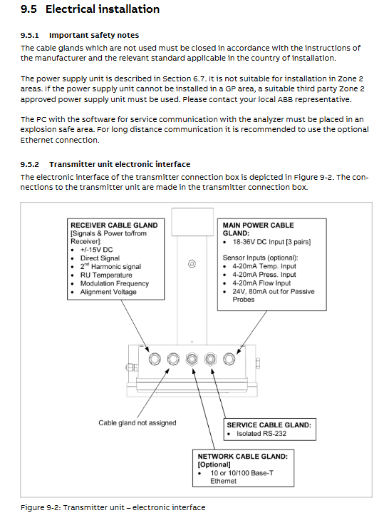
Transmission unit TU interface:
Receiver: TU-RU communication cable (power supply, modulation signal, second harmonic, temperature, alignment voltage);
Main power: DC18-36V power supply, multiple parallel connections; Simultaneously connect multiple 4-20mA external analog inputs (temperature, pressure, flow probes, support active/passive probes, board built-in 100 Ω sampling resistor, can be connected in series with multiple instruments);
RS-232 isolation debugging port;
RJ45 Ethernet.
Power supply unit: AC100-240V to DC24V; The power supply unit cannot be placed in an explosion-proof hazardous area (except for special requirements for explosion-proof versions).
AO2000 Central System Networking: Single and Multiple Analyzer Networking Topology; Distinguish between different Ethernet wiring schemes for AO2000 software V3/V4 versions and V5.00 and above versions; Cross switch networking requires switches to have at least 6 ports of 10/100M.
The board has fuses and status LEDs for quick diagnosis of power supply faults.
Range/Zero Calibration Options
Three hardware options are available for online verification without the need to remove the analyzer:
Circulating verification pool: Non corrosive gas, with standard gas introduced for Span verification.
External independent Span pool: used for corrosive gases.
Built in sealed standard chamber (with servo motor): The motor cuts the sealed reference chamber into the laser light path and performs Zero+Span calibration.
During calibration, the equipment will deduct the absorption of the process itself to obtain the gas reading in the calibration pool, which is used to determine drift.
Special Instructions for Explosion proof Version
CSA Class I Division2; ATEX Zone2 explosion-proof model
Explosion proof version hardware changes: adding a wiring junction box; The AC power supply unit must be arranged in a non hazardous safety area and cannot be placed in an explosion-proof area.
Cable glands and sealing joints must comply with explosion-proof specifications; Random replacement of components is prohibited as it may damage the explosion-proof certification.
The PC debugging computer must be placed in a secure area, with priority given to Ethernet remote debugging. It is not recommended to connect directly to RS232 on site.
Provide a complete terminal wiring table for the explosion-proof version, with cable length restrictions the same as the regular version.
Disposal of waste
The equipment belongs to the control of electronic and electrical waste under the WEEE directive and cannot be discarded as household waste. It should be handed over to professional recycling; ABB can also provide on-site recycling and disposal services for a fee.