ABB SYNCHROTACT ® 5 Synchronous devices
Overall advantages of the product
High reliability and availability, balancing anti misoperation and non-stop capability;
Reduce project implementation costs; Quick debugging and operation of PC tool SynView;
A device can support up to 7 different parameters and serve 7 different synchronous circuit breakers;
Mature technology, decades of experience in system engineering during the same period;
Rich interfaces, supporting multiple industrial buses;
After sales: 24-hour hotline 365 days a year, remote Internet maintenance, training courses for commissioning, operation and maintenance personnel.
II SYNCHROTACT ® 5 device application scenarios
Mainly used in power plants, self owned power generation industrial facilities, to achieve grid connection between generators and power grids/islanded lines, and also used in distribution systems. If the voltage, frequency, and phase are not synchronized and closed, it can cause line faults, generator overload, and in severe cases, damage to the generator. Supports three core working modes:
Automatic synchronization and grid connection of the generator to the power grid: output regulation pulses to the AVR automatic voltage regulator and GV speed controller, regulate voltage and frequency, and issue closing commands when conditions are met;
Automatic parallel connection between lines and busbars (synchronous/asynchronous circuits);
Synchrocheck monitoring mode: monitoring manual/automatic grid connection operations, supporting permission for closing dead bus without voltage.
Typical application wiring
Simultaneous inspection between simple lines;
Simultaneous verification and monitoring of manual grid connection;
Generator fully automatic synchronization;
With the help of auxiliary unit SYN5500, one host completes the synchronous switching of two circuit breakers.
Working principle
The entire synchronous logic is divided into four functional modules:
Measurement module: Collect U1 (system side) and U2 (standby side), calculate voltage difference Δ U, slip s (frequency difference), and phase angle α;
Matching regulation module: Output regulation pulses, regulate AVR voltage and speed regulation, reduce voltage and frequency differences;
Grid connection condition monitoring: Compare the measured values with the set limits, and if Δ U, s, and α all meet the conditions simultaneously, output CHK RELASE closing permission;
Generation of closing command: Considering the closing time of the circuit breaker, calculate the lead angle α v, and output the closing CMD when the phase reaches the lead angle and the permission is valid; Under steady-state synchronization, if the conditions are continuously met during the monitoring time, the command will be directly output.
Simultaneous inspection mode: Only enable measurement+condition monitoring, no voltage or frequency regulation, only output closing permission relay contacts.
Hardware model family (SYN-5xxx series)
Key Features of Model Core Functions
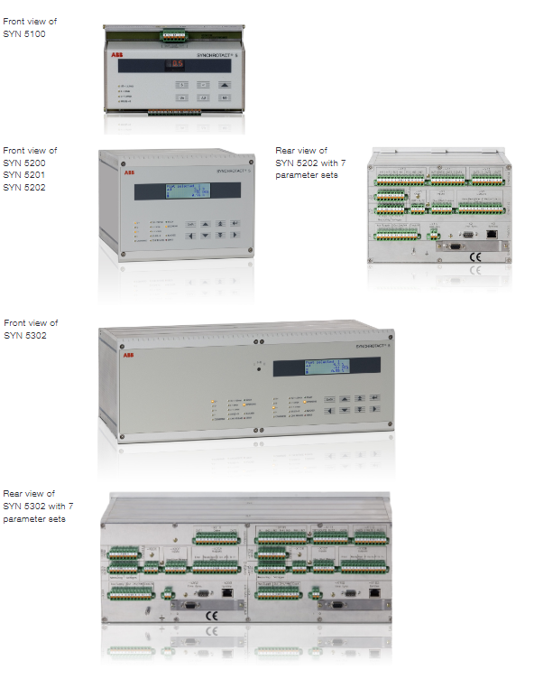
SYN 5100 only checks DIN rail installation synchronously with Synchrocheck, with only one set of parameter set and no automatic voltage and frequency regulation
SYN-5200 synchronous inspection/simple automatic grid connection, no matching regulator supports 7 sets of parameter sets, supports communication interfaces
SYN-5201 single channel fully automatic synchronization with voltage and frequency matching adjustment
SYN-5202 dual channel automatic synchronization with two independent software and hardware channels, connected in series to enhance the safety of preventing false closing
SYN 5302 The chassis is equipped with two complete sets of SYN5202, and one of the four output contacts can be bypassed internally. If one set fails, the other set will automatically take over, balancing safety and operational availability without the need for external redundant devices
Key selection points:
Low cost per channel; Dual channel with different software and hardware architectures, with extremely low probability of simultaneous failures, to avoid major equipment damage caused by grid connection errors;
SYN5302 integrates two complete dual channel systems into the same chassis, eliminating the need for external redundant cabinet wiring and engineering design.
Parameter set capability
Version with 7 parameter sets: stores 7 sets of independent and complete synchronous fixed values, corresponding to 7 different circuit breakers; By selecting parameter sets/synchronization points through numerical input, the software binds parameters with corresponding devices to avoid mismatched fixed values.
Control method
Local debugging and maintenance: The device comes with an LCD and buttons; Or PC software SynView (Ethernet);
Normal operation control: Hardwired DI/DO; Optional fieldbus remote control: Modbus RTU, Profibus DP, LON, IEC 61850 (Ethernet RJ45).
Order coding rules
SYN 5u0v‑wxyz
U0v: Product model; – w: Communication interface (0 none, 2 Modbus, 3 Profibus, 4 LON, 5 IEC61850); – x: Auxiliary voltage, rated frequency; – z: Number of parameter sets (1 set/7 sets).
Key technical specifications
Power supply
Auxiliary voltage: AC 100-230V/DC 24-250V;
SYN5100 power consumption 2W/4VA; SYN52xx/5302 has a maximum power of 25W/35VA.
Measurement input U1/U2: 50-130VAC, supports 16-2/3 Hz, 50 Hz, 60 Hz, measurement frequency range 10-100 Hz.
relay output
Closing relay: 250V AC/DC, continuous 10A; resistive connection 1500VA/W;
Adjustment and signal relay: 250V AC/DC, continuous 1.5A.
Parameter tuning range: slip limit, phase angle window, maximum voltage difference, dead bus criterion, voltage and frequency modulation pulse characteristics, circuit breaker closing time, and total synchronization time can all be customized; The pulse duration can be proportional to the difference or fixed in pulse mode.
Environment and Electromagnetic Compatibility
No communication model working -10~+55 ℃; Working with communication module+5~+55 ℃; Storage and transportation -40~+85 ℃;
Meet the IEC 60255 series relay protection standards; Vibration, impact, and earthquake testing; Static electricity, surge, fast transient, RF anti-interference; CE certification.
Structural protection: front panel IP54, rear panel IP50; Includes DIN rail and semi embedded panel installation.
Complete set of accessories
1. SynView PC Debugging Software (Windows Platform)
Five major functions:
Parameter tool: Read, write, save, compare device parameters, provide recommended constant value templates;
Real time numerical tool: Virtual synchronous table, visually displaying voltage, frequency, phase, and slip, can also be used for functional testing without on-site instruments;
Transient recorder: Save the complete synchronous full process curves of the last 3 times;
Event Recorder: Up to 256 timestamp events, convenient for locating wiring and controlling faults;
Diagnostic tool: Export internal diagnostic data and support ABB remote fault analysis.
Interface: Ethernet RJ45 or RS232.
2. SYN 5500 multi-channel synchronous switching auxiliary device
DIN rail installation; Used for multi-point synchronous circuit switching; One unit can switch between 2 synchronization points (up to 16 pairs of contacts per point) or 4 synchronization points (8 pairs of contacts per point), and can be cascaded and expanded by multiple units.
3. Simultaneous measuring instrument (96 × 96/144 × 144 panel meter)
Dual voltmeter SYN5Uxx;
Dual frequency meter SYN5Fxx;
Synchronization table SYN5Sxx; Used for manual synchronous panel display and automatic system operation and maintenance monitoring.
4. Adapt/compensate voltage transformer VT (SYN5T66-0001)
Solution scenario:
The secondary measurement voltage exceeds the rated input range of 50-130VAC;
The amplitude of the secondary voltage of PT on both sides is inconsistent;
The step-up transformer (Yd1/Yd11) causes an inherent 30 ° phase shift and requires phase compensation. Single phase adjustable ratio, capable of amplitude and phase compensation.
SYNCHROTACT ® CSS prefabricated integrated synchronous system
CSS is a factory prefabricated, complete set of synchronous device cabinet units that can be directly installed, wired, and debugged for operation, reducing on-site engineering design and improving safety. Internally based on SYNC HROTACT ® 5 hardware, supporting 19 inch rack installation.
Configuration Version
CSS-1100: Single channel, 1 circuit breaker;
CSS-1200: Single channel, 2 circuit breakers;
CSS-2100: Dual channel, 1 circuit breaker;
CSS-2200: Dual channel, 2 circuit breakers.
Working Mode
AUTO automatic mode: automatic voltage and frequency regulation, considering the precise closing delay of the circuit breaker;
MAN manual mode: Observation of panel instruments, manual button completion of grid connection;
TEST test mode: fully executes synchronous logic, but does not output a true closing command, only internal indication;
Support local/remote switching; The key switch allows the dead bus to close.
SynView software comes with the factory.
SYNCHROTACT ® Customized contemporaneous cabinet
Customize a complete synchronous cabinet according to project requirements, with only the core SYNC HROTACT inside the cabinet ® In addition, it can also integrate measurement and local operation control components. Flexible configuration:
Security architecture: single channel/dual channel;
Availability: redundant manual synchronization/redundant automatic synchronization;
Supports up to 4 circuit breakers (including generator circuit breakers);
Configurable redundant power supply;
Local/remote control;
PT voltage amplitude phase compensation.
Typical architecture example:
Dual channel automatic synchronization (SYN5202)+independent hardware redundancy manual synchronization check (SYN5200);
SYN5302 quadruple channel fully automatic redundant synchronization, with an additional manual synchronization path.