ABB UNITOL 1020 Compact Digital Excitation Regulator AVR
Application scope and product positioning
Applicable objects: Synchronous generators/synchronous motors, which can work in single machine islanding, grid connected, and multi machine parallel scenarios; Support PMG permanent magnet machine power supply, machine end transformer power supply, and external AC/DC power supply.
Working mode: Automatic voltage regulation AUTO, excitation current manual MAN, power factor PF, reactive VAR, open-loop Open Loop; Realize seamless switching between modes.
Optional software authorization package: Basic BASIC, Full Functionality, Independent Options (PSS Power System Stabilizer); Some advanced features require password activation, or pre activation can be ordered.
System architecture scheme
Single channel UNITOLO1020;
Dual channel DCH redundant system: Two UNITOLO1020s interact through the CAN bus, with one primary and one backup, and automatically switch in case of faults;
Paired with PM40 power expansion module, increase the excitation current from 20A to 40A;
Can be supplied in full container sets.
Key points of the safety chapter
Operator qualification: Only personnel who have received specialized training are allowed to install, debug, and maintain; Operators are not allowed to open the interior of the device.
Residual danger: The maximum internal voltage can reach 300V AC/DC; After a power outage, the internal large capacitor will still be charged, and the orange LED flashing indicates that the internal voltage is greater than 30V DC. It is necessary to wait for the discharge to be completed before disassembling.
High voltage operations must comply with EN 50110-1: power-off, anti misoperation closing, electrical testing, grounding short circuit, and isolation of adjacent live parts.
Emergency: Only CO ₂ fire extinguishers are allowed for electrical fires; Reminder: Magnetic fields pose a risk of interference with pacemakers.
Classification of hazard signs: DANGER (fatal), Warning (serious injury leading to death), CAUTION (equipment/personal injury minor), NOTICE (equipment damage).
Hardware Interface
3.1 Hardware of the main body
IP20 shell, aluminum backplate+top heat sink; IGBT power device, output short-circuit withstand.
Comes with 4 rows of LCD and 8 buttons for local HMI, capable of viewing and modifying all parameters, and supports cabinet door installation kit.
Terminal partition: power terminal, measurement terminal, digital I/O, analog I/O, communication terminal.
3.2 I/O Resources
Digital input DI (12 channels): configurable excitation switching, mode switching, synchronization enable, PSS switching, emergency stop excitation OFF, reset alarm, islanding/grid connected state, dead bus synchronization enable, etc; Support logic forcing (analog level without wiring), polarity can be independently set.
Digital DIO (8 channels, can be input/output multiplexed): Output configurable: synchronous closing permission, speed increase/decrease pulse, channel switching, various limiter action alarms, rotating diode fault alarm tripping, PSS activation, excitation input, soft start activation, etc.
Analog input AI (3 channels, -10V~+10V): external settings, cooling medium temperature, PSS injection signal, etc; Customizable range mapping.
Analog output AO (2 channels, -10V~+10V, maximum 10mA): capable of outputting excitation current, terminal voltage, active and reactive power, power factor, slip, Fbias frequency difference signal, PSS test points, etc., supporting range scaling.
3.3 All communication ports
Interface Usage Remarks
USB 2.0 connected to CMT1000 debugging software, with a maximum point-to-point cable length of 3m, capable of USB powered debugging
Ethernet Modbus TCP remote access and CMT1000 remote connection support SNTP timing; Up to one CMT1000 can be connected simultaneously, with multiple clients accessing via Modbus
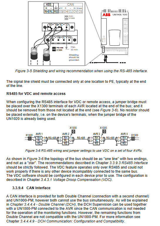
RS-485 Modbus RTU remote access/VDC reactive power sharing, choose one of two options; Multi machine parallel reactive power sharing dedicated bus; Maximum 500m, up to 31 devices
CAN bus dual channel DCH redundant interaction/external PM40 power module are mutually exclusive; The maximum length of the dual channel mode cable is 30m; it must be connected to a terminal resistor jumper
Important: RS-485 cannot simultaneously perform Modbus access and VDC; If needed simultaneously, VDC uses RS485 and Modbus uses Ethernet.
Overview of Software Functions
4.1 Operation and regulation mode
AUTO automatic voltage mode: PID regulation of generator terminal voltage; Support reactive power adjustment/compensation Kq.
MAN manual mode: directly adjust the excitation current PI closed-loop.
PF power factor mode/VAR reactive power mode: under grid connected conditions, adjust power factor or reactive power; Supports both direct and indirect adjustment algorithms.
Open Loop mode: Directly outputs PWM duty cycle without a closed-loop regulator.
Channel tracking Follow up: The set point of the inactive regulator automatically follows the current operating conditions to ensure undisturbed mode switching.
4.2 Startup Function
Soft Start: After excitation is activated, the voltage ramp increases; Support the second set of parameters for Line Charging line charging.
Field Flashing: The excitation pulse when the residual voltage is insufficient, and the shutdown level can be set.
Boost strong excitation: triggers strong excitation output when the terminal voltage drops, with threshold, hysteresis, and maximum holding time; PT fault locking strong excitation is possible.
FRT fault ride through detection: quickly identify voltage drops in the power grid, output contacts to the governor to reduce active power; Three phase measurement response is 20ms, single-phase response is 50ms.
Voltage matching VM: Automatically track the generator voltage to the grid voltage before grid connection.
4.3 Built in Sync option (software authorization)
Compared to the independent SyncHROTAC5: UNITOLO1020/1020, the synchronization is a built-in AVR function, suitable for small and medium-sized units; Large units are generally still equipped with independent SYNC HROTACT5 devices.
Measure Δ U voltage difference, slip s, and phase difference; Output voltage regulation commands to AVR, and output Fbias analog frequency difference signals or digital acceleration/deceleration pulses to the speed controller; Output the circuit breaker closing command when all conditions are met.
Support Dead Bus synchronization; Support the inherent phase offset caused by transformers such as Yd11, and configure angle offset parameter compensation.
Parameters can be set: maximum voltage difference, maximum and minimum slip, maximum phase angle, and total closing time of the circuit breaker.
Safety reminder: It is not recommended to rely solely on the built-in synchronization of the device. For important units, it is recommended to configure an independent synchronization check relay externally.
4.4 VDC voltage differential compensation (multi machine islanding reactive power sharing)
Through the RS-485 bus, multiple AVRs exchange reactive power data and automatically distribute the reactive power of each unit on the islanded bus; Supports ordinary bus segment topology and up to 8 segments in the ring network; The position of the identifiable circuit breaker can automatically change the reactive power grouping.
4.5 Complete set of limiters and monitoring protection
V/Hz (volt hertz) limit: prevents low-frequency overcurrent; Automatically lower the voltage setting value when the frequency drops.
Excitation current Ie limit: Three stage delay inverse time limit maximum and minimum excitation limits, supporting cooling temperature related derating.
PQ limiter: active reactive power boundary limitation, with a 5-point line defining the under excitation boundary.
Stator voltage limit, stator current IM limit (inverse time limit, temperature dependent), rotor field voltage limit.
Rotating diode monitoring RDM (optional): Rotating rectifier tube open/short circuit alarm, trip output.
DCH dual channel monitoring (single channel can also be enabled): 23 monitoring conditions, the configuration matrix determines which conditions trigger alarms and which direct excitation trips; Real time exchange of measurement quantities and set points between the main and backup channels on the CAN bus, with the backup channel tracking the main channel’s operating conditions and switching between faults without disturbance.
4.6 Recording function (Full feature package)
Data Logger, Event Recorder: Non volatile storage that stores fault and event sequences for accident recovery.
4.7 PSS power system stabilizer (independent paid option)
Suppressing low-frequency oscillations in the power system; Support external signal injection testing.
4.8 Access and Permissions
Local panel;
CMT1000 PC software;
Modbus TCP/Modbus RTU remote read and write parameters, set points; The parameter modification must be saved to EEPROM and not lost when powered off.
Installation, Storage, and Disposal
Mechanical installation: The installation environment is dry with less dust; Pay attention to the electrical impulse current on the device.
External capacitor ExCap: It can be connected to a 1000 µ F/450V capacitor to extend the lifespan of power devices. Strictly pay attention to polarity, as reverse connection can directly damage hardware.
Storage conditions; Guidelines for equipment disposal, disassembly, and recycling.
Operation and commissioning
Debugging is divided into three stages:
Unit static state: hardware wiring inspection, forced I/O testing, communication inspection, parameter input (PT/CT ratio, unit rated parameters, limiter settings).
No load test (rated speed, not connected to the grid): excitation, soft start, voltage regulation range test, limiter test, voltage matching test.
Load and synchronous grid connection test: synchronous logic verification, load regulation mode switching, PQ limitation, VDC reactive power sharing test. After the operation is completed, it is necessary to backup and save the complete parameter file.
Operation
Front panel HMI: Start stop STOP/START button, menu browsing, set point modification, alarm viewing, EEPROM saving; Emergency excitation OFF button.
CMT1000 software (Windows)
Parameter read/write backup, PID tuning Tune menu;
Oscilloscope recording;
Event and data recorder reading;
VDC monitoring and DCH dual channel status diagnosis;
Software authorization password activation.
Control priority: Hardwired DI/DO has the highest priority, higher than panel and remote Modbus commands.
Maintenance and troubleshooting
Preventive maintenance: terminal fastening, inspection of heat dissipation ducts, inspection of status indicator lights, backup of parameter files.
Troubleshooting: List of fault phenomena, locate alarm codes through panel and CMT1000 reading;
Spare parts strategy: The dual channel DCH system can replace boards separately; Single channel recommended spare parts for the entire machine.
Key Technical Data
Excitation output UNITOLO1020 body: continuous 20A DC; Short term overload indicator; The maximum duration of the PM40 module is 40A.
Auxiliary control power supply: AC 100-230V/DC 18-300V; Power supply AC/DC 0-300V.
Measurement input: maximum terminal voltage of 250VAC, CT secondary 1A.
Working temperature: 0-60 ℃; Storage -20~+75 ℃; UL certification; EMC complies with relevant industry standards.
Mechanical dimensions: Width 170mm x Height 302mm x Depth.