
-2%

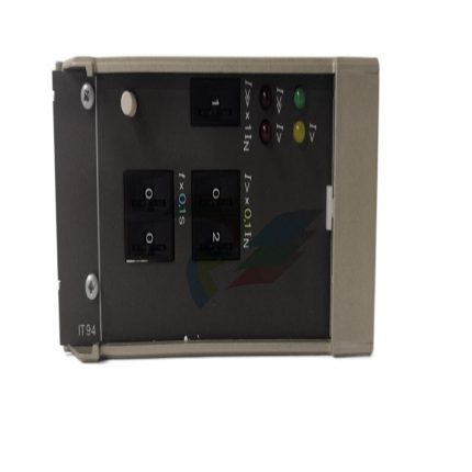
ABB 57619414 A 2/2 connector module
Original price was: $7,937.00.$7,037.00Current price is: $7,037.00.个
ABB LDSTA-01 63940143B Input/Output (I/O) Module
Original price was: $9,505.00.$8,483.00Current price is: $8,483.00.个
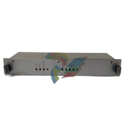
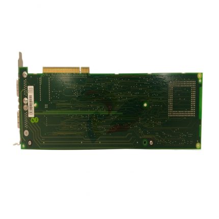
ABB LDMTR-01 63940135F Input/Output (I/O) Module
Original price was: $9,059.00.$8,848.00Current price is: $8,848.00.个
The ABB LDMTR-01 63940135F input/output (I/O) module is a core peripheral device in ABB industrial automation control systems, designed specifically for signal acquisition and control instruction execution in industrial sites. This module, with its high reliability, strong anti-interference ability, and flexible adaptability, is widely used in complex industrial scenarios such as power, metallurgy, chemical, and manufacturing industries. It can achieve precise acquisition of on-site sensor signals and stable control of actuators, providing key signal transmission and conversion support for the efficient operation of automation systems.
Description
ABB LDMTR-01 63940135F Input/Output (I/O) Module
Basic overview of module
The ABB LDMTR-01 63940135F input/output (I/O) module is a core peripheral device in ABB industrial automation control systems, designed specifically for signal acquisition and control instruction execution in industrial sites. This module, with its high reliability, strong anti-interference ability, and flexible adaptability, is widely used in complex industrial scenarios such as power, metallurgy, chemical, and manufacturing industries. It can achieve precise acquisition of on-site sensor signals and stable control of actuators, providing key signal transmission and conversion support for the efficient operation of automation systems.
As an important component of ABB’s automation product system, this module strictly follows industrial grade design standards and can adapt to harsh on-site environments, including wide temperature operation, electromagnetic interference prevention, vibration resistance, etc., ensuring continuous and stable operation under complex working conditions, effectively improving the overall reliability and operation efficiency of the system.
Core functions and roles
2.1 Signal acquisition and conversion
The module has the ability to process multiple types of input signals and can accurately collect analog signals (such as current, voltage signals, commonly used in sensor outputs such as temperature, pressure, flow, etc.) and digital signals (such as switch status, pulse signals, used to detect equipment start stop, valve opening and closing, etc.) from industrial sites. The collected on-site signals are filtered, amplified, isolated, and processed by the signal conditioning circuit inside the module, and then converted into standard digital signals that can be recognized by the control system, achieving information exchange between the on-site status and the control system.
2.2 Control instruction execution
After receiving control instructions from the main controller (such as PLC, DCS), the module converts them into analog or digital signals that can be responded to by industrial actuators, driving actuators such as valves, motors, indicator lights, etc. to achieve precise control of the production process. For example, adjusting the opening of the regulating valve by outputting the corresponding current signal according to the controller instructions, or outputting a digital signal to control the start and stop of the motor.
2.3 Signal isolation and protection
The module is equipped with built-in optoelectronic or electromagnetic isolation units, which provide electrical isolation between input/output signals and internal circuits of the module, as well as between the module and the main controller, effectively suppressing electromagnetic interference (EMI), common mode interference, etc. in the industrial field, and avoiding false triggering or damage to the system caused by interference signals. At the same time, the module has overcurrent and overvoltage protection functions. When the input signal is abnormal or the output load is overloaded, it can automatically cut off the circuit or limit the current, protecting the safety of the module and external equipment.
2.4 Diagnostic and Communication Functions
Support online self diagnosis function, which can monitor the working status of the module in real time (such as power failure, communication abnormality, channel failure, etc.), and feedback the diagnostic information to the main controller through the communication interface, making it easy for operation and maintenance personnel to quickly locate the fault. The module adopts standardized communication protocols (usually adapted to ABB dedicated buses or industrial Ethernet protocols), which can achieve high-speed and stable data exchange with the main controller, supporting real-time data transmission and fast response to instructions.
Key technical parameters
input parameters
Analog input
Supports common industrial standard signals such as 4-20mA current signal and 0-10V voltage signal, with input impedance ≥ 100k Ω and accuracy ± 0.1% FS
Digital input
Support NPN/PNP switch signals, input voltage 24V DC, response time ≤ 1ms
Number of input channels
According to the specific configuration, it is usually 8/16 channels (refer to the product manual for accurate values)
output parameters
Analog output
Output range 4-20mA (load ≤ 500 Ω), 0-10V (load ≥ 1k Ω), accuracy ± 0.2% FS
digital output
Relay output/transistor output, 24V DC/220V AC, rated current 2A/circuit
Number of output channels
Match with the number of input channels, usually 8/16 channels (refer to the product manual for accurate values)
Power and Environment
working power supply
24V DC ± 10%, power consumption ≤ 10W
working environment
Temperature -20 ℃~60 ℃, humidity 5%~95% (no condensation), protection level IP20 (module body)
Communication and isolation
communication interface
Supports ABB S800 I/O bus or industrial Ethernet protocols such as Profinet/EtherNet/IP
Isolation level
Isolation between input/output/power supply, isolation voltage 2500V AC (1 minute)
Installation and wiring specifications
4.1 Installation Requirements
-The module needs to be installed on a standard DIN rail, and the installation position should be away from strong electromagnetic interference sources (such as frequency converters, high-power motors) and high-temperature heat sources (such as heaters, boilers), avoiding direct sunlight.
-At least 5mm of heat dissipation gap should be reserved between modules to ensure good ventilation and prevent performance degradation or failure due to overheating.
-During installation, handle with care to avoid severe vibration or impact, and prevent damage to the internal circuits of the module.
4.2 Wiring specifications
-Before wiring, it is necessary to confirm that the system power has been cut off to avoid short circuits or electric shock accidents caused by live operation.
-The input/output signal lines should use shielded twisted pair cables, with the shielding layer grounded at one end (grounding resistance ≤ 4 Ω) to enhance anti-interference capability; The power line and signal line should be wired separately to avoid parallel laying.
-Strictly follow the module terminal diagram for wiring, ensuring that the input signal type matches the module channel (e.g. analog input channels cannot be connected to strong voltage signals), and the output channel load must not exceed the rated value.
-After the wiring is completed, it is necessary to check whether the wiring terminals are tightened to avoid signal abnormalities caused by poor contact.
Common faults and troubleshooting methods
Fault phenomenon
Possible reasons
troubleshooting method
The module power indicator light is not on
1. The power supply is not connected; 2. Power line malfunction; 3. The module power interface is damaged
1. Check if the power switch is closed and if the power voltage is normal; 2. Check if the power cord wiring is loose or broken; 3. Try replacing the power supply. If it still doesn’t light up, repair the module
No response to input signal
1. Sensor malfunction; 2. Input line disconnection or poor contact; 3. Module input channel failure
1. Check if the sensor output signal is normal; 2. Check the input circuit wiring and measure the continuity of the circuit with a multimeter; 3. Replace the input channel for testing and confirm if it is a channel fault
Abnormal output signal
1. Main controller instruction error; 2. Short circuit or overload of output line; 3. Module output channel fault
1. Check if the output instructions of the main controller are normal; 2. Disconnect the load and measure the output signal of the module. If it returns to normal, it is a load problem; 3. Replace the output channel for testing and confirm if it is a channel fault
Communication failure
1. Communication line wiring error; 2. Communication protocol mismatch; 3. Module communication interface failure
1. Check whether the communication line wiring meets the protocol requirements (such as positive and negative poles, bus terminal resistance); 2. Confirm that the communication parameters between the module and the main controller are consistent; 3. Replace communication cables or modules for testing
Maintenance and Precautions
-Regularly check the working status of the module, including indicator light display, temperature, and wiring terminal fastening. It is recommended to conduct a routine inspection once a month.
-When cleaning the module, the power should be cut off, and a dry soft cloth should be used to wipe the surface dust. Avoid using water or corrosive cleaning agents to prevent water or corrosion inside the module.
-The maintenance of module faults should be carried out by professional technicians. It is prohibited to disassemble the module without authorization to avoid damaging the internal circuit or affecting the warranty.
-When replacing a module, it is necessary to ensure that the new module model is consistent with the original module (63940135F is the key model identification). After replacement, parameter configuration and calibration need to be carried out again to ensure compatibility with the system.
Additional information
| Weight | 2.6 lbs |
|---|---|
| Dimensions | 36 × 261 × 15 in |
Reviews (0)
Shipping and Delivery


Reviews
There are no reviews yet.