
-18%
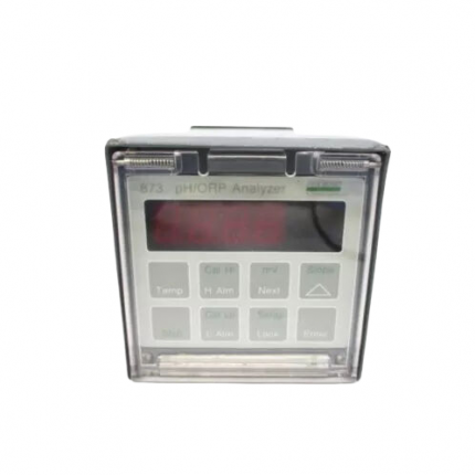
 [USED] FOXBORO 873EC-JIPFGZ-5")
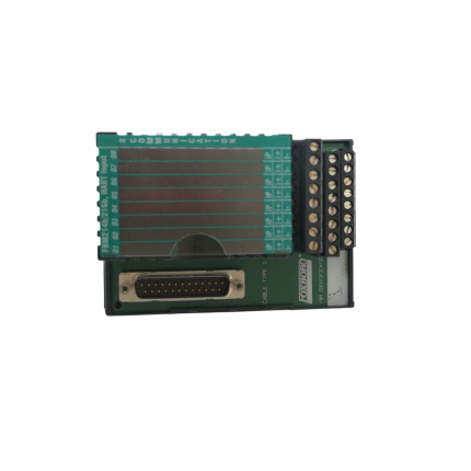
FOXBORO RH926GH processor module
Original price was: $9,568.00.$8,835.00Current price is: $8,835.00.个

FOXBORO P0926GJ high-precision differential pressure transmitter
Original price was: $19,674.00.$15,857.00Current price is: $15,857.00.个

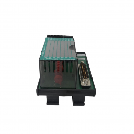
FOXBORO H90 H90C9AA0117S Differential Pressure Transmitter
Original price was: $9,684.00.$7,894.00Current price is: $7,894.00.个
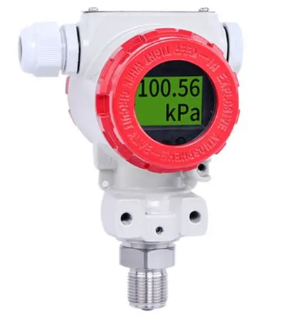
The FOXBORO H90C9AA0117S differential pressure transmitter is the core model of the H90 series under the Foxboro brand of Schneider Electric. It is designed specifically for the precise measurement of differential pressure in industrial processes and is an intelligent process measurement device with high reliability. This model inherits the mature capacitive sensing technology and intelligent signal processing solution of the H90 series, which can stably monitor the differential pressure parameters of liquids, gases, or vapors, thereby achieving indirect measurement and control of key process parameters such as liquid level, flow rate, and pressure. As an important supporting instrument for industrial automation control systems, H90C9AA0117S has good system compatibility and can be seamlessly integrated with mainstream distributed control systems (DCS). It is widely used in multiple industrial fields such as petrochemicals, power, water treatment, metallurgy, etc., providing accurate and reliable data support for process optimization and safety protection.
Description
FOXBORO H90 H90C9AA0117S Differential Pressure Transmitter
Product Overview
The FOXBORO H90C9AA0117S differential pressure transmitter is the core model of the H90 series under the Foxboro brand of Schneider Electric. It is designed specifically for the precise measurement of differential pressure in industrial processes and is an intelligent process measurement device with high reliability. This model inherits the mature capacitive sensing technology and intelligent signal processing solution of the H90 series, which can stably monitor the differential pressure parameters of liquids, gases, or vapors, thereby achieving indirect measurement and control of key process parameters such as liquid level, flow rate, and pressure. As an important supporting instrument for industrial automation control systems, H90C9AA0117S has good system compatibility and can be seamlessly integrated with mainstream distributed control systems (DCS). It is widely used in multiple industrial fields such as petrochemicals, power, water treatment, metallurgy, etc., providing accurate and reliable data support for process optimization and safety protection.
Detailed performance parameters
Accuracy and stability parameters
H90C9AA0117S, with mature sensing technology and precise signal processing algorithms, performs excellently in accuracy and stability, meeting the high-precision measurement needs of industrial grade:
Measurement accuracy: ± 0.1% (reference accuracy, based on full range), stable measurement accuracy can be maintained throughout the full range;
Repeatability: ± 0.05%, ensuring consistency of multiple measurement results and providing assurance for the stability of process control;
Long term stability: ± 0.2%/year. During long-term continuous operation, the measurement accuracy of the equipment deteriorates slowly, effectively reducing maintenance costs caused by frequent calibration;
Temperature effect: After precise temperature compensation, the temperature error is ≤ ± 0.1%/10K, and stable measurement performance can be maintained over a wide temperature range.
Pressure and Range Parameters
The equipment has flexible range adjustment capability and strong adaptability to meet the differential pressure measurement needs of different industrial scenarios
Standard measurement range: 0~1kPa to 0~10MPa (differential pressure), can be flexibly configured according to actual working conditions;
Unidirectional overload pressure: up to 3 times the measurement range (specific value depends on the actual configuration range), with strong impact resistance, and can adapt to scenarios with instantaneous pressure fluctuations in working conditions;
Range ratio: The adjustable range ratio can reach up to 50:1. Users can adjust the range through a HART controller or on-site buttons, without the need to replace equipment, to meet the measurement needs of different working conditions;
Static pressure tolerance: The maximum static pressure can reach 16MPa, and it can stably measure small differential pressures in high-pressure environments, suitable for high-pressure vessels, pipelines, and other working conditions.
Environmental and Protection Parameters
The equipment adopts a fully sealed structure design, which has excellent environmental adaptability and protective performance, and can cope with the challenges of harsh industrial environments:
Working temperature range: -20 ° C to+85 ° C, can adapt to the temperature environment of most industrial sites;
Storage temperature range: -40 ° C to+100 ° C, convenient for transportation and storage in low or high temperature areas;
Relative humidity: 0~100% (allows short-term condensation), can operate stably in high humidity environments;
Protection level: IP65, with complete dust prevention and protection against low-pressure water spray in any direction, suitable for industrial sites with high dust and humidity;
Anti interference capability: It has strong electromagnetic interference (EMI) and radio frequency interference (RFI) protection capabilities, complies with the IEC 61000 series industrial electromagnetic compatibility (EMC) standards, and ensures signal stability in strong electromagnetic environments.
Power and Communication Parameters
Power supply voltage: 12~42VDC, supports 24VDC standard industrial two-wire power supply, compatible with mainstream industrial power systems;
Output signal: Standard 4-20mA analog signal, combined with HART digital communication signal, communication rate meets BELL202 standard;
Display and operation: Optional built-in LCD display screen and physical operation buttons, supporting multilingual display in Chinese, English, etc., can display measurement values, range, fault codes and other information in real time, convenient for on-site debugging and parameter setting; The model without display can be fully configured through a HART controller.
Installation and commissioning precautions
Preparation before installation
-Site inspection: Select installation locations that meet the requirements of the equipment environment, avoid high temperature heat sources, strong vibration sources, strong magnetic fields, and corrosive gas environments, ensure that the installation site is flat, ventilated, and has sufficient space for operation and maintenance; If measuring high-temperature media, a condenser ring needs to be installed to avoid direct impact of high temperature on sensor performance;
-Equipment inspection: After opening the box, check whether the equipment model (confirm H90C9AA0117S) and specifications are consistent with the order, check whether the appearance and components of the equipment are intact, and whether the accessories (such as installation brackets, wiring terminals, instructions, calibration certificates) are complete. If there is any damage or missing, contact the supplier in a timely manner for handling;
-Preparation of tools and materials: Prepare installation tools and materials such as screwdrivers, wrenches, drills, sealing gaskets, shielded cables, etc., ensuring that the accuracy of the tools meets the installation requirements, and that the cable specifications match the power and signal transmission requirements of the equipment (it is recommended to use shielded twisted pair cables);
-Safety protection: Installation personnel need to wear protective equipment such as safety glasses and insulated gloves. If the site involves high voltage and corrosive media, corresponding explosion-proof and anti-corrosion protective equipment should also be equipped to ensure the safety of the installation process.
Installation specifications
-Installation and fixation: Select the appropriate installation method (thread/flange) according to the on-site working conditions, fix the equipment on the installation base, use a level to adjust the equipment to a horizontal state, ensure firm fixation, and avoid vibration affecting measurement accuracy; If installed on a pipeline, it is recommended to install it perpendicular to the flow direction of the medium, and the sensor position should be lower than the pressure point to facilitate the discharge of condensate;
-Media connection: When connecting the tested media pipeline, ensure that the interface is well sealed. Fluororubber or polytetrafluoroethylene sealing gaskets can be used to enhance sealing and avoid media leakage; For corrosive media, it is necessary to confirm that the material of the connecting pipeline is compatible with the material of the equipment isolation membrane; After the connection is completed, the pressure valve should be slowly opened to remove air and impurities from the pipeline;
-Electrical wiring: Strictly follow the equipment wiring diagram to connect power and signal lines, using a two-wire wiring method to ensure correct and secure wiring, avoiding short circuits or poor contacts. The equipment must be reliably grounded, with a grounding resistance of less than 4 Ω, and neutral wires must not be used instead of ground wires; The shielding layer of shielded cables should be grounded at one end (preferably at the control system end), and cable wiring should avoid parallel laying with strong current cables to reduce electromagnetic interference;
-Protective measures: In dusty, humid, or outdoor environments, additional sealing protection should be applied to the equipment junction box to ensure that the equipment protection level is not lower than IP65 requirements; If there is an explosion-proof requirement on site, it is necessary to ensure that the equipment installation meets the explosion-proof level requirements, and it is strictly prohibited to disassemble the equipment in explosive environments.
Debugging Process
-Before powering on, check again whether the power supply voltage (ensure it is 12-42VDC) and wiring method are correct, confirm that the equipment is firmly fixed, well sealed, and free of looseness or leakage;
-Power on test: After connecting the power supply, observe whether the device’s LCD display screen (if optional) lights up normally and whether there are any fault code prompts; The model without a display screen can read the device status through a HART handheld device. If there is a malfunction, it is necessary to promptly disconnect the power and troubleshoot wiring or equipment issues;
-Parameter configuration: The device can be configured with parameters such as measurement range, units (such as kPa, MPa, mH ₂ O), damping time (0.1-60 seconds), output signal type, communication address, etc. through a HART controller or on-site buttons (if optional) to ensure that the parameter settings are consistent with the on-site operating conditions and control system requirements; After configuration, save the parameters to EEPROM;
-Zero point and range calibration: Perform zero point calibration in the absence of pressure input; Connect to a standard pressure source (with an accuracy more than three times that of the equipment), perform range calibration, and ensure that the measured values of the equipment are consistent with the standard pressure values, with errors within the allowable range; During the calibration process, calibration data needs to be recorded as a maintenance file;
-Functional testing: Simulate on-site working conditions, change the input differential pressure value, test whether the equipment measures response speed, signal stability, and alarm function to see if they are normal; Read the diagnostic information of the device through the HART handheld device, confirm that there are no abnormalities in the device, and ensure that all functions meet the usage requirements.
Maintenance and troubleshooting
Daily maintenance and upkeep
-Regular inspection: Conduct a weekly visual inspection of the equipment to check for damage or leaks in the casing and seals, as well as loose or oxidized wiring terminals; Check monthly whether the measured values of the equipment match the actual working conditions on site, and determine whether the measurement accuracy is normal;
-Cleaning and maintenance: Regularly clean the dust and oil stains on the surface of the equipment, disconnect the power supply during cleaning, use a dry and soft cloth to wipe, and avoid using corrosive cleaning agents; For isolation membranes, it is necessary to carefully clean the residual media attached to the surface to avoid scratching the membrane;
-Regular calibration: According to the operating conditions and accuracy requirements of the equipment, a comprehensive calibration should be conducted every 1-2 years to ensure that the measurement accuracy of the equipment meets the standard requirements. Calibration should be carried out by professional personnel using standard pressure sources, calibration instruments, and other professional equipment, and calibration records should be kept and maintenance files established;
-Replacement of vulnerable parts: Regularly inspect the aging and damage of equipment sealing gaskets, O-rings, and other vulnerable parts. Replace the sealing gaskets every 6 months to avoid medium leakage or decreased measurement accuracy due to sealing failure; If the equipment operates in a corrosive environment for a long time, the replacement cycle of vulnerable parts needs to be shortened.
Common faults and solutions
Fault phenomenon
Possible reasons
solution
No 4-20mA signal output, display screen does not light up (optional)
1. Abnormal power supply voltage or power outage; 2. Loose wiring, short circuit or poor contact; 3. Internal circuit failure of the equipment; 4. The fuse is blown
1. Check the power supply voltage and power supply circuit to ensure that the voltage is within the range of 12-42VDC; 2. Re tighten the wiring terminals, investigate short circuit issues, and replace damaged cables; 3. If there are no problems with the above investigation, contact professional personnel to repair the internal circuit of the equipment; 4. Check the built-in fuse of the equipment and replace it with a fuse of the same specification if necessary
Excessive or unstable measurement deviation
1. Zero point or range not calibrated; 2. Isolation membrane blockage, damage, or residual adhesion medium; 3. Leakage of filling fluid; 4. The ambient temperature exceeds the allowable range; 5. Parameter settings are incorrect (such as range, damping time); 6. Blockage or leakage of pressure pipeline
1. Perform zero and range calibration again; 2. Clean the surface residue of the isolation membrane. If the membrane is damaged, it needs to be replaced; 3. Check the sealing area, add filling fluid and repair the seal; 4. Improve the installation environment to ensure that the temperature meets the requirements; 5. Verify and correct equipment parameter settings; 6. Clean the pressure pipeline and repair the leaking area
HART communication failed, unable to remotely configure
1. Communication protocol parameters do not match (such as communication address, baud rate); 2. Communication line failure or poor grounding of shielding layer; 3. The HART handheld device is not compatible with the equipment; 4. Equipment communication module failure; 5. The power supply voltage is too low to support communication function
1. Verify and unify the communication parameters between the device and the HART controller; 2. Check communication lines, repair broken wires or poor contacts, and ensure reliable grounding of the shielding layer; 3. Confirm the compatibility between the HART handheld device and the equipment, and update the firmware of the handheld device; 4. Repair or replace the communication module of the equipment; 5. Check the power supply voltage to ensure that it is not lower than 12VDC
The output signal remains constant at 20mA (upper limit) or 4mA (lower limit)
1. Input pressure exceeds the measurement range (overload); 2. Sensor malfunction; 3. microprocessor malfunction; 4. Parameter configuration error (such as setting the range too small)
1. Check the on-site working pressure to ensure that it does not exceed the measurement range of the equipment; 2. Read the sensor status through the HART handheld device, and if the sensor malfunctions, it needs to be repaired or replaced; 3. Restart the device and attempt to recover. If it fails, repair the microprocessor; 4. Reconfigure the range parameters to ensure that the range is suitable for the on-site working conditions
Equipment leakage
1. The sealing gasket is aging or damaged; 2. Loose connection interface; 3. The isolation membrane has ruptured; 4. Damage to the casing or cavity
1. Replace aging or damaged sealing gaskets; 2. Tighten the connection interface; If the isolation membrane ruptures, contact a professional to replace the sensor unit; 4. Check for damage to the casing or cavity, and replace the equipment casing if necessary
Safety Maintenance Standards
-Before maintenance, the power supply of the equipment must be disconnected. If it needs to be reconnected after the power is cut off, the interval should be at least 1 minute to avoid frequent power on and off damage to the internal circuit;
-When maintaining the parts in contact with the medium, it is necessary to first cut off the transmission pipeline of the measured medium, close the pressure valve, release the residual pressure and medium inside the equipment, and avoid personal injury or environmental pollution caused by medium leakage;
-The maintenance of core components such as internal circuits and sensors of the equipment must be carried out by trained professional technicians. Non professionals are strictly prohibited from disassembling them without authorization to avoid equipment damage or safety accidents;
-If there is a major malfunction of the equipment (such as internal short circuit, shell rupture, large leakage of medium, etc.), it should be immediately stopped from use, the power and medium connection should be disconnected, warning signs should be set up, and Foxboro official technical support or authorized service providers should be contacted for maintenance;
-When conducting maintenance in explosive environments, it is necessary to strictly comply with explosion-proof safety regulations, and it is strictly prohibited to carry out maintenance operations without cutting off power or eliminating the risk of explosion.
Additional information
| Weight | 0.6 lbs |
|---|---|
| Dimensions | 477 × 357 × 342 in |
Reviews (0)
Shipping and Delivery


Reviews
There are no reviews yet.