TOSBERT VF-AS3 Industrial Inverter Quick Start Manual
1. Basic information
Product positioning: Used for controlling the speed of three-phase induction motors, built-in permanent magnet synchronous motors (IPMSM), and surface permanent magnet synchronous motors (SPMSM) in industrial scenarios, and cannot drive single-phase motors
Voltage and power range:
500V level: 1.5kW-55kW
600V (575V) level: 2HP-75HP (HD)/3HP-100HP (ND)
690V level: 2.2kW-75kW (HD)/3kW-90kW (ND)
Core features: Supports multiple ratings (HD/ND), V/f control, vector control, PID control, built-in EMC filter and DC reactor
2. Core security standards
2.1 Personnel and Protection Requirements
Qualification requirements for homework types require necessary protective equipment
All qualified installation/maintenance personnel shall wear protective gloves and safety work clothes
Electrical work requires the qualification of insulated gloves, insulated shoes, and anti electric shock clothing
High altitude operations (≥ 50cm) require industrial safety helmets with high-altitude operation qualifications and ladders that comply with ISO14122 standards
Shoes for heavy object transportation (≥ 20kg) without special qualifications but requiring training on anti smashing toe caps
Qualified maintenance personnel with electrician specific protective gloves for maintenance operations
2.2 Key safety taboos
High voltage operation: After power failure, wait for 15 minutes (capacitor discharge), confirm that the charging light is off and the DC voltage is ≤ 45V before operation
Prohibited behavior:
Do not disassemble the front cover/small front cover (including high-voltage components inside) while it is live
Do not connect the power supply to the output terminals [U/T1] [V/T2] [W/T3]
Do not modify equipment or use non specified accessories
Prohibit the use of welding machines in enclosed spaces (to prevent carbon monoxide poisoning)
Power requirement: Do not connect the corner grounding system, IT system needs to disconnect the grounding capacitor
3. Installation and wiring
3.1 Installation environment and conditions
Remarks on the Range of Environmental Parameter Requirements
If the ambient temperature is between -15 ℃ and+60 ℃ and exceeds 50 ℃, it is necessary to reduce the capacity for operation
Relative humidity 5%~95%, no condensation
Altitude ≤ 2000m>1000m, capacity reduction of 1% per 100m
Vibration ≤ 5.9m/s ² (10-55Hz) Avoid installation in locations with high vibration
Installation location: Indoor, no direct sunlight, no corrosive gas/oil mist, ventilation space needs to be reserved
3.2 Installation and wiring specifications
Installation method:
Wall mounted installation: NEMA Type 1 kit is required (NEM301Z for A1Y, NEM302Z for A2Y)
Multiple parallel devices: A1Y spacing ≥ 11mm, A2Y spacing ≥ 11mm, with a ventilation space of ≥ 10cm reserved above and below
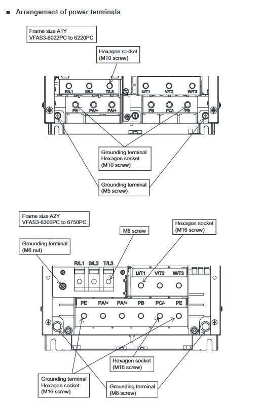
Wiring requirements:
Power terminal: [R/L1] [S/L2] [T/L3] (three-phase input)
Motor terminals: [U/T1] [V/T2] [W/T3] (three-phase output)
Grounding terminal: [PE], wire diameter needs to be matched (such as 600V HD type 12AWG corresponding to grounding 12AWG)
Terminal torque: A1Y 12AWG is 26.5lb · in, A2Y output terminal is 363lb · in
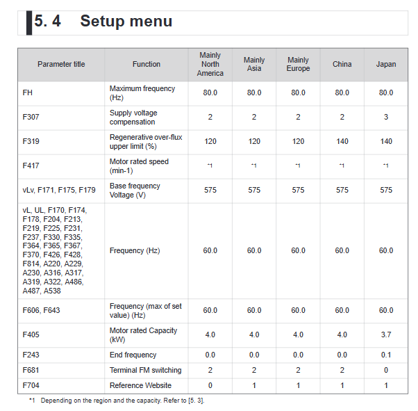
4. Parameter settings
4.1 Core Parameters (Basic Settings)
Parameter Name Function Adjustment Range Default Settings
CMOd (Command Selection) Select the control mode terminal/operation panel/communication, etc. 0 (terminal)
FMOd (frequency command selection) Select frequency control source terminal/touch screen/communication, etc. 1 (terminal RR)
ACC (Acceleration Time 1) Acceleration Time from 0Hz to FH 0.0~6000s 10.0s
Deceleration time from FH to 0Hz for dEC (deceleration time 1) is 0.0~6000s 10.0s
FH (maximum frequency) output frequency upper limit 30.0~590.0Hz 80.0Hz
AUL (Multiple Rating Selection): Select HD/ND and voltage levels 2 (ND-600V), 3 (HD-600V), etc. 3 (HD-600V -60Hz)
4.2 Differences in Multiple Rated Values (HD/ND)
Rated Value Type Overload Capacity Applicable Scenario Parameter Setting (AUL)
HD (Heavy Duty) 150% -60s constant torque load (conveyor, crane, etc.) 3 (600V), 15 (500V), 17 (690V)
ND (Normal Duty) 120% -60s variable torque load (fan, pump, blower, etc.) 2 (600V), 14 (500V), 16 (690V)
5. Standard compliance measures
5.1 Main Compliance Standards
Key measures for compliance requirements of standard types
The EMC directive complies with IEC61800-3, CISPR11 with built-in EMC filters, shielded cables, and separate wiring
Low voltage instructions comply with IEC61800-5-1 for installation in cabinets, standardized grounding, and installation of protective devices
UL/CSA standards comply with UL61800-5-1, using UL certified cables and installing specified fuses/circuit breakers
ATEX directive not applied for and cannot be used in explosion-proof scenarios
5.2 Short circuit protection configuration (UL/CSA standard)
Inverter Model Maximum Voltage (V) Branch Circuit Protection (Fuse) Power Wire Specification (AWG) Grounding Wire Specification (AWG)
VFAS3-6022PC 600 Class J,10A 12 12
VFAS3-6110PC 600 Class J,25A 10 10
VFAS3-6300PC 600 Class J,60A 4 2
VFAS3-6750PC 600 Class J,150A 1/0 2
6. Product specifications and warranty
6.1 Core specifications (taking 600V HD type as an example)
Model Applicable Motor (HP) Output Capacity (kVA) Output Current (A) Cooling Method Weight (kg)
VFAS3-6022PC 2 3.1 3.1 Forced Air Cooling 21.6
VFAS3-6110PC 10 13 13.5 Forced Air Cooling 21.6
VFAS3-6300PC 30 34 34 forced air cooling 51.9
VFAS3-6750PC 75 83 83 Forced air cooling 52.5