Programming Guide for Modicon 884 Programmable Controller
The Programming Guide for Modicon 884 Programmable Controller (PI-884A-001 Rev C) is designed for use with AEG/Modicon 884 series PLCs and P190 programmers. It covers the entire process of hardware operation, power on process, I/O configuration (Traffic Cop), ladder logic programming, basic operations, data transmission, matrix/special functions and fault codes, passwords, maintenance, etc. The core is used for industrial control logic development, system configuration and debugging, clarifying memory specifications, communication parameters, address rules and operation constraints.
P190 Programmer Core Operation
Keyboard partition: letter keys, number keys, function keys, software label keys
Key switch:
Memory Protect: Lock=monitoring mode (read-only); Unlock=Programming Mode (modifiable)
Peripheral port: RS-232C, supports 50~19200 baud, default 9600, even parity, 1 stop bit
Magnetic tape drive: used for loading software and programs, requiring protection against erasures
Power on and operational hierarchy
Power on level (Attach): Insert the tape → Load → Connect to PC (press Attach for direct connection, set addresses 1-247 for multiple stations)
Operation level:
START PC/STOP PC: Start stop controller
PC OPS: Clear memory, configure, initialize
Program: Enter Logic Programming
CONFIG: Enter I/O configuration
DETACH: Disconnect communication
PC Operation (PC OPS)
Function Description
CLEAR PC clears all memory/user logic/registers
PC CONFIG settings scan (constant 1~195ms/free running), port parameters
Initiate TABLE initialization configuration/Traffic Cop/User logic table
Device address hardware switch setting, default 001
I/O configuration (CONFIG core)
Core tool: Traffic Cop: Map I/O modules and addresses, match physical slots
Configuration item:
Channels (1~maximum), racks (1~5), slots (1~11)
Module type: B802~B899
Reference address: Discrete/Register, Data type BCD/BINARIY
Constraint: Maximum 32 slots per channel, maximum 512 I/O points
diagnosis:
HEALTH: Checking module status during operation
MISMATCH: Shutdown to check configuration and physical differences
WRITE CHNL: Must be executed to save configuration
Fundamentals of Trapezoidal Logic Programming
Network: Maximum 11 columns x 7 rows, with the 11th column being the coil area
Reference address rule:
0XXXX: Coil/Output
1XXXX: Discrete Input
2XXXX: Sequencer
3XXX: Input register
4XXXX: Keep Register
5XXXX: Double precision register
SXXXX: Latch
Contact type: normally open/normally closed/rising edge/falling edge
Coil: Normal (power-off state), Locked (power-off hold)
Scanning order: top left → bottom right, executed column by column and line by line
Two editing modes
Element Editor: Online modification, real-time writing to PC
Network Editor: Offline editing, batch replacement/insertion/swapping of networks, supports FLIP NET rollback
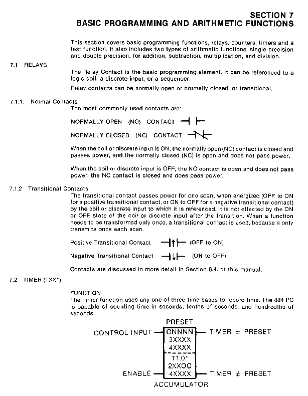
Basic functions (timer/counter)
Timer (T1.0 seconds/TO.1 seconds/T.O1 0.01 seconds): preset value ≤ 9999
Counter:
UCTR: Counting Up
DCTR: Countdown
Preset ≤ 9999, trigger to avoid counting per scan
Computational function
Single precision (≤ 9999): ADD/SUB/MULT/DIV/TEST
Double precision (± 8 bits, 5XXXX): DADD/DSUB/DMUL/DDIV
TEST: unsigned comparison, output>/=/<three results
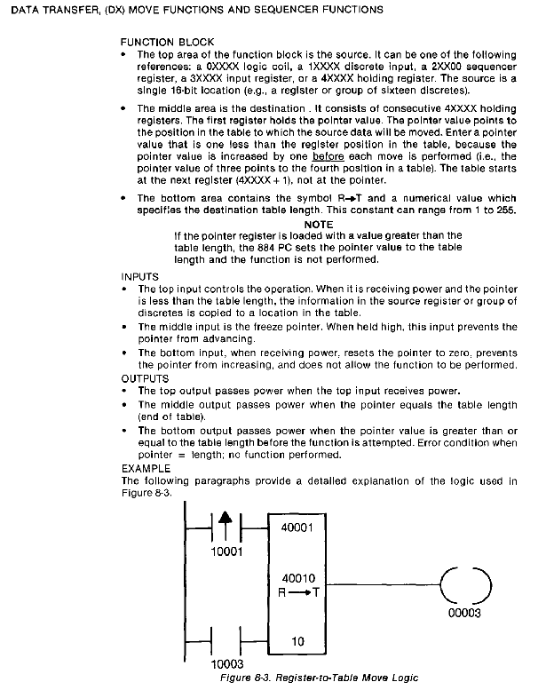
Data transmission DX function
Movement: T → R, R → T, BLKM (block movement, up to 100)
Sequence: SEQ (single point sequence), DRUM (multi-point sequence)
Latch (LTCH): SXXXX address, power down hold
Matrix:
BSHL/BSHR: Left/Right Shift
BSEN: Bit detection
MBIT: Position modification
Matrix with a maximum length of 100 registers (1600 bits)
Special Features
SKIP: Skip up to 255 networks to reduce scanning time
OK: Monitor variable/I/O health status
STAT: Collect I/O faults to the table
X ↔ 5: Single precision ↔ Double precision conversion
Appendix Key
Error codes are divided into three categories: panel communication, PC link, and user operation
Password level:
Level 0: Read only
Level 1: Modify reference, start stop
Level 2: Modify logic and parameters
Level 3: Configure I/O, Change Password
Memory specifications: minimum 2K user logic, 1K registers, 256 discrete I/O
Key questions and answers
Question: What is the Traffic Cop function of Modicon 884? What steps must be taken after configuration? Answer: Traffic Cop is used to map and bind the physical location of I/O modules with program addresses, define data types (BCD/BINARIY), and verify module matching; After the configuration is completed, it must be saved by pressing WRITE CHNL+PROCESS, otherwise the configuration will be lost.
Question: How to classify the reference addresses of 884 PLC? What functions do they correspond to? Answer: The address is classified by the first digit:
0XXXX: coil/discrete output; 1XXXX: Discrete Input
2XXXX: Sequencer; 3XXX: Input register
4XXXX: Keep register; 5XXXX: Double precision register
SXXXX: Lock (power down hold)
Question: What is the function of the memory protection switch of P190 programmer? What operations are restricted by the two modes? Answer: Memory protection switch controls operation permissions:
Lock (monitoring mode): can only view programs I/O、 Configuration, unable to modify memory, start stop PC
Unlock (programming mode): can modify logic, clear memory, configure I/O, start stop controller