PILZ PNOZ m B0 configurable safety control system basic unit
The English operation manual (1002660-EN-05) for the PILZ PNOZ m B0 configurable safety control system basic unit, as the core basic unit of the PNOZmulti 2 series, supports IEC 61131-3 programming and multiple buses such as EtherCAT and Modbus. It has 4 safety outputs, 12 dedicated inputs, 8 mixed I/O, and 4 test pulse outputs, and can achieve PL e/Cat.4/SIL CL 3 safety level. The program can be downloaded through a chip card or USB, and comes with an LCD screen, rotating knob, and LED for local diagnosis. It is suitable for industrial safety circuits such as emergency stop, safety door, and dual hand control.
Core hardware configuration
Type Quantity/Specification Description
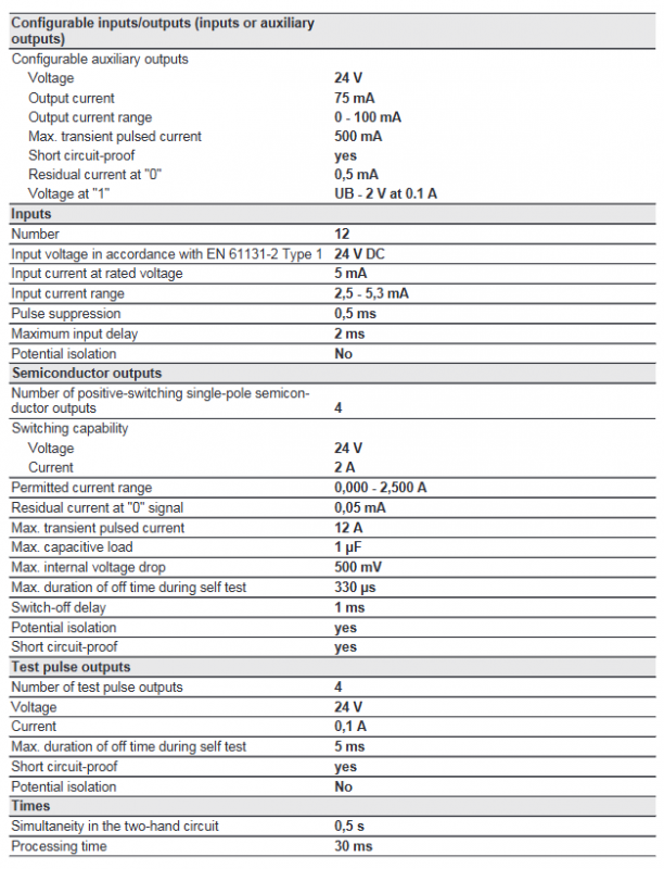
12 dedicated inputs for emergency stop, safety door, grating, reset, PSEN, etc
8 configurable I/O channels (IM0~IM3, IM16~IM19) can be set as inputs or auxiliary outputs
Safe output 4-channel (O0~O3) semiconductor output, 2A/channel, safety level
Test pulse output, 4-channel monitoring input short circuit, cannot be loaded
4-channel configurable auxiliary output, non safety function
Storage chip card (8KB/32KB) storage configuration project
Interface USB, extension interface download program, connection extension module
Security Performance (Core)
Architecture: Dual MCU redundancy, built-in self-monitoring, maintains safety function in case of failure
Highest level:
PL e / Category 4(EN ISO 13849-1)
SIL CL 3(EN IEC 62061)
Service life: TM=20 years
System response time: 30ms
Operation and Display
LED indicator light
PWR: Power Supply
RUN: Run
DIAG: Diagnosis
Fault: Total malfunction
I FAULT: Input fault
O FAULT: Output fault
LCD display screen
Display I/O status, error messages, project information, and device information
Error Stack: Stores up to 64 errors
Rotate the knob
Can be pulled out/rotated/pressed for menu navigation, confirmation, and reset
Long press for 3-8 seconds to execute project download/device reset
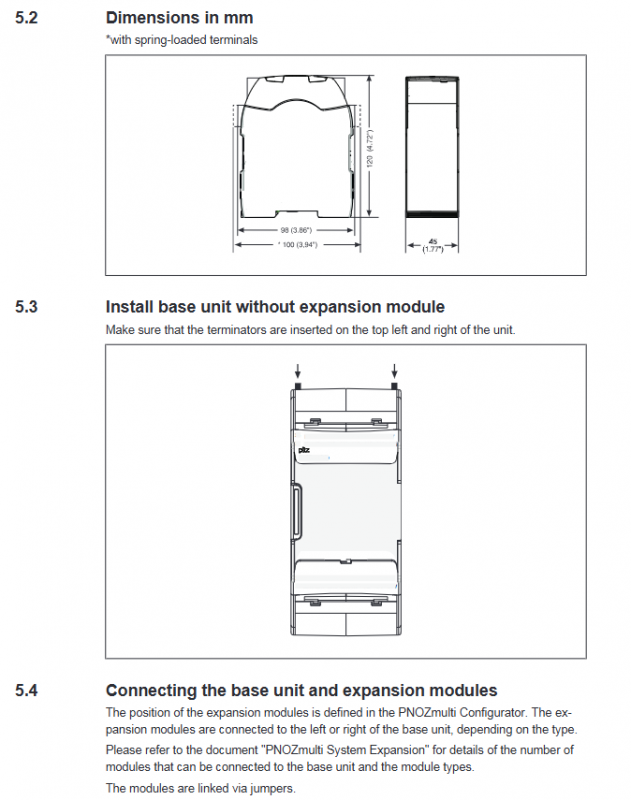
Installation specifications
Installation method: DIN rail vertical installation, heat sink facing up and down
Installation spacing: Above/Below * * ≥ 30mm * *, Both sides * * ≥ 20mm**
Protection requirements: Installed in control cabinets with an IP54 rating or higher
Expansion connection: To connect the expansion module through jumper wires, a terminal must be installed
Anti static: Static electricity must be released before operation
Wiring and power supply
System power supply: 24VDC (A1/A2), fluctuation -20%~+25%
Output power supply: 24VDC, can be isolated independently from the system power supply
Wiring terminal: optional spring or screw type
Wire: 75 ℃ heat-resistant copper wire, inductive load requires protection
Test pulse line: cannot be laid in the same cable as the power line
Debugging and Program Download
Two download methods
Chip card: Insert → Power on → Long press knob for 3-8 seconds to load
USB: Connect to computer → Download through PNOZmulti Configurator
Mandatory requirement: Functional testing must be conducted after each download/card replacement/reset of the project
Chip card usage: power off insertion and removal, keep the contacts clean and without bending
Technical parameters
Working temperature: 0~+60 ℃
Storage temperature: -25~+70 ℃
Input current: 5mA/channel (24VDC)
Safe output voltage drop: ≤ 500mV
Size: 101.4 × 45 × 120 mm
Weight: 235g
Maximum wiring distance: Input 1km, test pulse 2km
Ordering Information
Basic Unit: PNOZ m B0, Order Number 772100
Attachment: Terminal, USB cable, spring/screw terminal
Key questions and answers
Question: How to allocate the input and output of PNOZ m B0? What are the electrical restrictions for safe output?
Answer: Configure 12 dedicated safety inputs, 8 configurable I/O, 4 safety semiconductor outputs, and 4 test pulse outputs; The safety output is 24VDC, with a maximum of 2A per circuit and short-circuit protection. Inductive loads require protection and cannot be used for ordinary loads outside of safety functions.
Question: How does the controller achieve the highest level of safety? What are the specific certification indicators achieved?
Answer: Adopting dual MCU redundant architecture+hardware self-monitoring+output short circuit monitoring; It can achieve PL e, Category 4 (EN ISO 13849-1), and SIL CL 3 (EN IEC 62061), which is the highest level of industrial safety circuits.
Question: What are the local diagnostic methods for PNOZ m B0? How to reset after a malfunction occurs?
Answer: Diagnosis includes 6 LED status lights, LCD text prompts, and an error stack (up to 64 entries); After troubleshooting, press and hold the knob for 3-8 seconds to perform a reset, or select the reset item or restart the device from the menu.