PILZ PNOZmulti Classic and PNOZmulti Mini configurable safety controllers
Product positioning and core advantages
Product positioning
Fill in the safety control scheme between safety relays and large PLCs
Classic: ≥ 4 security features, fully modular expansion
Mini: ≥ 3 safety features, compact small point solution
core advantage
PNOZmulti Configurator graphical software, no code required
Highest PL e/Cat. 4/SIL CL 3 safety level
Rich fieldbus and * * distributed I/O (IP67) * * support
Multi level diagnosis to reduce downtime
System Architecture and Expansion Rules
1. General architecture
Basic unit+expansion module+bus terminator
Modules are connected through jumper wires, and a terminal must be installed at the end
2. Maximum scalability of Classic
Maximum number of expandable modules for location
4 left link/analog/bus modules
8 input/output/speed monitors on the right side
16 distributed PDP67 IP67 modules
3. Maximum scalability of Mini
Maximum number of expandable modules for location
Left link/communication/bus module 4+1+1
1 PNOZsigma output module on the right side
16 distributed PDP67 IP67 modules
Security Performance (Core)
Architecture: Dual MCU redundancy+hardware self-monitoring
Highest security level
PL e / Category 4(EN ISO 13849-1)
SIL CL 3(EN IEC 62061)
Service life: 20 years
Typical reaction time
Input delay: 4ms
Semiconductor output shutdown: 30ms
Relay output shutdown: 50ms
List of Core Modules
1. Classic Basic Unit
Special scenario for model positioning
PNOZ m0p Basic Universal Security
PNOZ m1p Extended Universal Security
PNOZ m2p specialized mechanical press
PNOZ m3p special burner/furnace safety
2. Key expansion modules
Input: PNOZ mi1p (8 secure inputs), mi2p (8 standard inputs)
Analog quantity: PNOZ ma1p (2-channel safe analog quantity, voltage/current)
Output: mo1p (4-channel safety semiconductor), mo4p (4-channel safety relay)
Links: ml1p (system cascade), ml2p (distributed module)
Speed monitoring: MS series (1-2 axes, supporting incremental encoders)
Bus: Supports EtherCAT, PROFIBUS, Profinet, CANopen, CC Link, etc
3. Mini basic unit
Model characteristics
PNOZ mm0p is not expandable
PNOZ mm0.1p expandable+local display
PNOZ mm0.2p with built-in Multi Link cascading
Software and Configuration
Tool: PNOZmulti Configurator
Process: Select hardware → Draw security logic → Download to chip card/USB
Function:
Emergency stop, safety door, hands, light barrier, mute, speed/static monitoring
Macro library reuse, password protection, multilingual
Automatically calculate safety level PFH/PFD
Diagnostic system
Local diagnosis
LED:PWR/RUN/DIAG/FAULT/I FAULT/O FAULT
Error stack: Save up to 64 faults
remote diagnosis
Serial/Ethernet/Bus Read Diagnostic Words
Support PASvisu visual monitoring
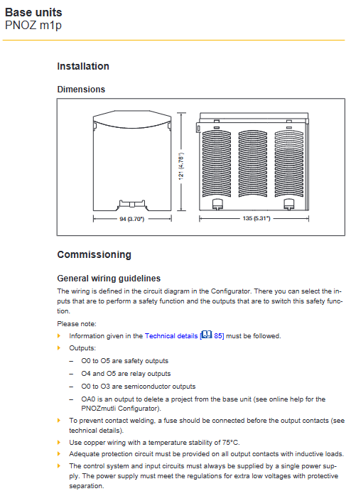
Installation and wiring specifications
Install
Method: DIN 35mm rail horizontal installation
Spacing: Up and down * * ≥ 30mm * *, left and right * * ≥ 20mm**
Protection: IP54 inside the cabinet, IP20 for the module body
wiring
Power supply: 24VDC, ripple ≤ 5%
Terminal: spring/screw, torque 0.25~0.5N · m
Wiring: Separate the testing pulse line and power line for installation
Key issues
Question: What are the core positioning differences between PNOZmulti Classic and Mini, and what scenarios are they suitable for?
Answer: Classic is a standard modular safety controller that supports complete expansion and specialized models (press/burner), suitable for medium to large equipment with ≥ 4 safety functions; Mini is a compact device with small size and limited expansion, suitable for small devices with ≥ 3 safety functions and distributed safety points.
Question: How does this series of controllers achieve the highest level of safety? What are the safety levels for single and dual channel input and output?
Answer: By relying on dual MCU redundancy, hardware self-monitoring, and output short circuit monitoring, the highest safety can be achieved. Single channel input/output can reach PL d/Cat.2/SIL CL 2; Dual channel can achieve PL e/Cat.4/SIL CL 3.
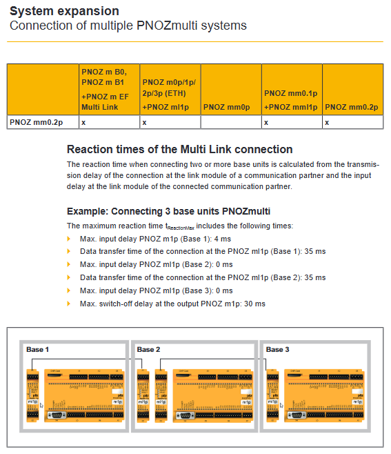
Question: How is the system response time calculated? What is the maximum response time for Classic basic unit+semiconductor output as an example?
Answer: Total response time=maximum input delay+maximum output shutdown delay. The input delay of the Classic basic unit is 4ms+the semiconductor output is turned off for 30ms, totaling a maximum of 34ms.