Renishaw PHC10-3 PLUS Probe Controller Installation Guide
Renishaw PHC10-3 PLUS probe controller installation guide, used to guide the installation, wiring, communication configuration, and troubleshooting of PH10 PLUS series electric probes. The equipment supports RS-232/USB dual communication interface, 24V DC power supply, 13 configuration switches, LED status diagnosis, and PICS interface, which can directly replace the old PHC10-2 and meet the high-precision motion control requirements of CMM coordinate measuring machines. It complies with FCC Class A, CE, and BS EN61010-1 standards.
Environmental and electrical parameters
Project specifications
Protection level IP30
Working temperature: 0~+50 ℃
Storage temperature -10~+70 ℃
Altitude ≤ 2000m
Power supply 100~240VAC 50/60Hz
Power module Emerson DP4024N3M, 24VDC 49W
Maximum input current 1A
Pollution level 2
Panel and Interface
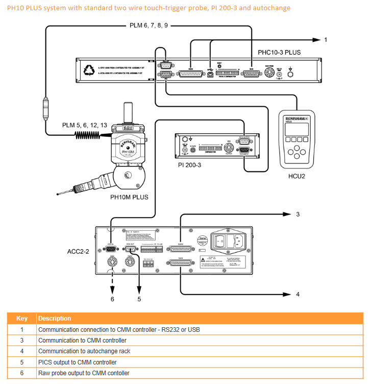
1. Core interface of the rear panel
Number interface function
9-pin D-type PICS output
2 9-pin D-type HCU2 manual control unit
3 25 pin D-type RS-232 (connected to CMM)
4 USB-B USB communication
5. Configuration of dip switch system
6 15 pin D-type probe connection
7-pin DIN original probe signal
8 DC socket 24V power supply
9 Grounding pole equipotential connection
10 Reset button for system restart
2. Front panel LED indicator light
POWER (green): The power supply is normal
STOP (red): System stop/error
HEAD READY (green): Probe ready
HEAD ACTION (yellow): The probe is in motion
DATUM/OBSTRUCT/OVRLOAD (red): benchmark error/blocking/overload
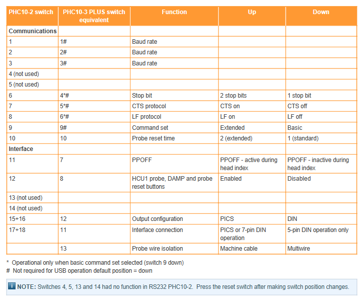
13 configuration switches (core)
Definition of switch function up/down
1~3 baud rate combination setting 300~19200
4 stop positions UP=2 bits/DOWN=1 bit
5 CTS protocol UP=ON/DOWN=OFF
6 LF Line Break UP=ON/DOWN=OFF
7 PPOFF mode division is valid/invalid
8 HCU2 Function UP=Enable/DOWN=Disabled
9 Instruction Set UP=Extension/DOWN=Basic
10 probe reset time UP=extended/DOWN=standard
11 interface mode PICS/DIN or 5-pin DIN
12 output configuration PICS/DIN
13 cable isolation machine line/multi-core wire
Attention: After modifying the switch, the reset button must be pressed to take effect.
Communication configuration
1. RS-232
Format: 1 start bit+7 data bits+1 check bit+1/2 stop bit
Baud rate (switches 1-3):
300/600/1200/2400/4800/9600/19200
Instruction set:
Basic: Compatible with old systems, protocol configurable
Extended: New protocol supporting HCU2/PICS software control
2. USB
Interface: USB-B, automatic switching priority
Requirement: Install a dedicated driver with a maximum cable length of 5m
Attention: Cannot be connected simultaneously with RS-232, unplugging the cable will trigger STOP
PICS interface signal (critical)
Pin signal function
1 STOP low level valid, error stop
PPOFF probe prohibition signal
3 0V public ground
5/9 Probe signal probe triggers output
7 PDAMP probe damping to reduce false triggering
Installation specifications
Size: 440 × 44 × 180 mm, weight 1.5kg
Installation method:
Desktop: equipped with rubber foot pads
Rack: 19 inch standard rack
Wiring requirements:
The internal resistance of the probe cable is ≤ 2.5 Ω
Continuous connection of shielding layer to reduce interference
Maintenance and troubleshooting
Maintenance: There are no user repairable parts, and any malfunctions need to be returned to the factory; Wipe the surface with a dry cloth
Typical faults:
The power light is not on: check the 24V power supply and emergency stop
Probe not moving: check wiring, baud rate, instruction set
Measurement error: loose probe, damping not closed
STOP trigger: overload, cable disconnection, USB hot plug
Key issues
Question: What is the main difference between the PHC10-3 PLUS and the old PHC10-2? What should be noted when upgrading? Answer: PHC10-3 PLUS has added USB communication, removed IEEE interface, and adjusted the layout of Rear interface, but the types are compatible; Simplify and consolidate the dip switches into one row. When upgrading, simply refer to the switch mapping table configuration, and after modification, press the reset button to directly plug and play the replacement.
Question: In what scenarios are the RS-232 and USB communication methods of PHC10-3 PLUS used? What are the restrictions? Answer: RS-232 is used for old CMM systems and requires baud rate/stop bit/instruction set settings; USB is used for new systems, plug and play, and faster. Restriction: Cannot access simultaneously; The maximum length of USB cable is 5 meters; USB disconnection triggers STOP; Switches 1-6 are invalid in USB mode.
Question: What are the functions of PPOFF and PDAMP signals in the PICS interface of PHC10-3 PLUS? In what scenario is it used? Answer: PPOFF is a probe power prohibition signal used to cut off and trigger the probe during indexing to avoid misoperation; PDAMP is a damping signal used to reduce the sensitivity of the CMM probe during rapid movement, prevent false triggering of vibration, and restore normal detection after reaching the position. Both work together to enhance measurement stability and safety.