MITSUBISHI ELECTRIC FR-A500 Series Inverter Manual
Product and Safety Overview
Product range:
Model: FR-A520 (200V), FR-A540 (400V)
Power: 0.4K~55K (kW)
Type: Transistor inverter, focusing on high functionality and low noise
Security level (must be followed):
Warning: Incorrect operation may result in death/serious injury
It is strictly prohibited to open the front cover when powered on/running
Wait for ≥ 10 minutes after power failure and confirm that there is no residual voltage
Must be grounded (PE) in accordance with IEC 60364, NEC 250
CAUTION: Incorrect operation may cause injury/damage to equipment
Installed on non combustible materials
It is strictly prohibited to connect power factor capacitors, surge absorbers, and filters on the output side
The main power contactor cannot be used for frequent start stop operations
Installation and environmental requirements
Project specifications
Constant torque at ambient temperature: -10~+50 ℃; Variable torque: -10~+40 ℃
Humidity ≤ 90% RH (non condensing)
Vibration ≤ 5.9m/s ²
The installation direction must be vertical, with a ventilation distance of ≥ 5cm/10cm above and below
Installation inside the protective cabinet to prevent oil mist, dust, and water droplets
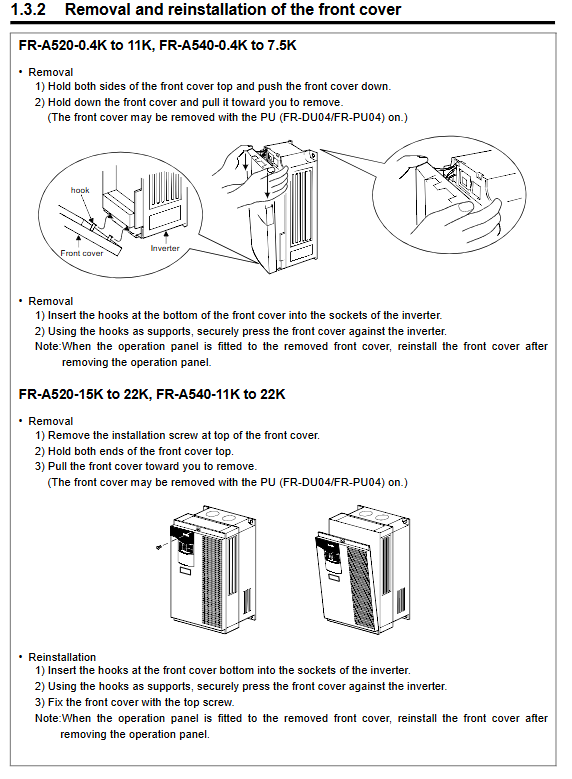
Installation points:
Grasp the body, do not grip the front cover
Foreign objects must not fall into the machine
Multiple units installed side by side need to ensure proper ventilation ducts for heat dissipation
Wiring (Core)
1. Main circuit terminal
Key requirements for terminal function
R/S/T three-phase power input must not be connected to U/V/W
U/V/W frequency converter output → It is strictly prohibited to connect capacitors/filters to the motor
R1/S1 control circuit power supply can independently supply power and maintain alarm output
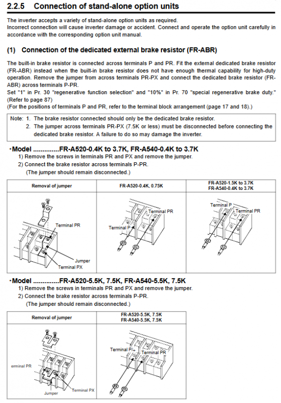
P-PR brake resistor connected to 7.5K or below with built-in brake
Remove the jumper and reconnect the P-P1 DC reactor connection
Grounding body grounding thick wire, short distance, independent grounding
2. Control circuit terminals (commonly used)
Terminal function
STF forward rotation start
STR Reverse Start
RES reset (effective for ≥ 0.1s)
AU current input (4-20mA) is valid
RH/RM/RL multi-stage speed selection
A/B/C alarm relay output
FM/AM frequency/analog meter output
Wiring taboos:
Separate wiring for the main circuit and control circuit, using shielded twisted pair cables for control
The total length of the output line is ≤ 500m, and the carrier frequency needs to be reduced for long distances
Operation and Running Mode
Operation panel: FR-DU04
Buttons: MODE switch mode, SET confirm, FWD/REV forward and reverse, STOP/RESET stop reset
Display: Frequency/Current/Voltage/Alarm
4 operating modes (Pr.79 setting):
External mode (default): Terminal control start stop+analog/multi-stage speed setting
PU mode: direct panel operation
Combination mode: external start stop+PU frequency or PU start stop+external frequency
Communication mode: RS485 controlled by the upper computer
Basic operation process: Wiring check → Power on → Confirm EXT/PU indicator light → Set frequency → Start → Monitor → Stop
Parameter system (core)
Required basic parameters
Parameter Number Name Typical Value/Range Description
Pr.0 torque increase 0-30% low-frequency torque compensation
Pr.1 Maximum frequency 0~120Hz output upper limit
Pr.2 Minimum frequency 0~120Hz output lower limit
Pr.3 Base frequency 50/60Hz motor rated frequency
Pr.7 acceleration time 0~3600s 0 → 60Hz time
Pr.8 deceleration time 0~3600s 60 → 0Hz time
Pr.9 electronic overcurrent relay motor rated current motor thermal protection
Pr.79 operation mode selection 0~8 external/PU/combination
Advanced functional parameters
Multispeed: Pr.4-6, Pr.24-27, Pr.232-239 (up to 15 speeds)
PID control: Pr.128-134 (proportional/integral/derivative)
Instant power outage restart: Pr.57, Pr.58, Pr.162
Vector control: Pr.80~96 (motor capacity, number of poles, automatic tuning)
Frequency jump: Pr.31-36 (avoid mechanical resonance)
Parameter protection: Pr.77 (0=shutdown writable, 1=prohibit writing, 2=run writable)
Protection function and alarm
Typical protection projects:
Overcurrent E.OC1-3
Overvoltage E.OV1-3
Undervoltage E.UVT
Overload E.OL
Overheated E.OH
Output phase loss, CPU failure, communication abnormality
Fault handling:
After alarm: investigate the cause → reset RES terminal or panel → restart operation
Retry function (Pr.65-69): Automatically retry after alarm, up to 10 times
Maintenance and repair
Daily inspection:
Cooling fan, abnormal heating, peculiar smell, abnormal noise, loose terminals
Regular inspection:
Main circuit voltage, insulation, capacitor lifespan, and cleaning of heat sinks
Prohibited items:
Do not perform megohmmeter (shake meter) testing on the control circuit
Lifespan components:
Cooling fan, electrolytic capacitor (Pr.504 set alarm time)
Specifications and Options
standard specifications
Input: Three phase 200V/400V, 50/60Hz
Control mode: PWM control, Soft PWM low noise
Carrier frequency: 0.7~14.5kHz (Pr.72)
Overload capacity: 150% for 1 minute
Common options
FR-ABR braking resistor
FR-BAL/FR-BEL Reactor
FR-BIF noise filter
FR-A5NR communication module
Key issues (3 different focuses)
Question 1: Why is it strictly prohibited to connect capacitors, surge absorbers, or filters on the output side (U/V/W) of the frequency converter?
answer:
The output of the frequency converter is high-speed PWM pulses, containing a large amount of high-frequency harmonics;
Capacitors can form high current charging and discharging circuits, directly causing overcurrent tripping (E.OC) of the frequency converter and even burning of the power module;
Surge absorbers/filters can resonate with output harmonics, causing overheating, damage, and false protection;
Specification: Filters and reactors can only be installed on the input side (R/S/T).
Question 2: What is the function of Pr.79 operating mode? What control methods correspond to commonly used settings?
Answer: Pr.79 is used to switch between start stop and frequency given sources, and is the most commonly used parameter for on-site debugging:
0: Switching mode when power is turned on (EXT/PU)
1: PU mode (panel operation only, safest)
2: External mode (terminal start stop+external simulation/multi-stage speed, factory default)
3: Combination mode (external start stop, PU set frequency)
4: Combination mode (PU start stop, external frequency setting)
5-8: Communication/Fixed Mode, etc
Question 3: What are the three most common reasons and troubleshooting steps for the motor not rotating and the panel not sounding an alarm?
answer:
Operation mode mismatch
EXT lights up but starts with the panel/PU lights up but starts with the terminal → switch to Pr.79 mode.
Start/frequency signal not effectively inputted
External mode: STF/STR not conducting, frequency set to 0V, AU not turned on (4-20mA).
Protect or restrict actions
The startup frequency Pr.13 is too high, the lowest frequency Pr.2 is 0 but insufficient, and the MRS output stop signal is valid.
Troubleshooting sequence: Confirm mode → Check indicator light → Check terminal voltage → Check parameter limits.