Instructions for using LK-TECH MGv2 servo motor
Product series and positioning
MGv2 is a leader control integrated deceleration and small backlash integrated servo, paired with DG80R/C7 driver, designed for high-precision, high response, and high torque scenarios.
Comparison of the Four Major Servo Series:
Application of Series Advantage Voltage, Current, and Speed Control
MS low-speed stable 7.4-24V 0-4A 0-1000rpm SVPWM gimbal and pod
MF high-speed high-precision 12-36V 0-9A 0-3000rpm FOC pan tilt and turntable
MG built-in gearbox, small backlash 24-48V 0-14A 0-2000rpm FOC foot/exoskeleton robot
MH large and medium-sized hole shaft 12-24V 0-4A 0-3000rpm FOC gimbal, radar
Drive core parameters (DG80R/C7)
Parameter values
Input voltage 12-60V DC
Rated current 10A
Maximum current 20A (lasting for 10 seconds)
Torque loop frequency 32KHz
Speed/Position Loop 8KHz
PWM frequency 32KHz
Torque bandwidth 0.4-2.8KHz
Encoder accuracy 18 bits
Communication RS485/CAN
Interface and wiring
1. Definition of motor interface
Pin function
A/H RS485-A / CAN-H
B/L RS485-B / CAN-L
V+positive pole of power supply
V – Negative pole of power supply
T/R UART debugging
G signal ground
2. Bus wiring rules
RS485/CAN bus must have 120 Ω terminal resistors connected at both ends
Use XT30 interface for power supply, and it is strictly prohibited to connect the positive and negative poles in reverse
Debugging using USB-UUART (CP210x) to connect to a computer
Model Naming Rules
MG 80 16 -i6 E 18bit RS485
MG: Series
80: Stator diameter
16: Stator height
I6: Reduction ratio 1:6
E: Dual encoder
18 bit: Encoder accuracy
RS485: Communication method
Upper computer software (LingKong Motor Tool V2.33)
1. Installation and connection
Install CP210x USB to serial port driver
Open the software, select COM port, baud rate 115200 ID1
Click Connect, the green light stays on, indicating a successful connection
2. Core configuration page
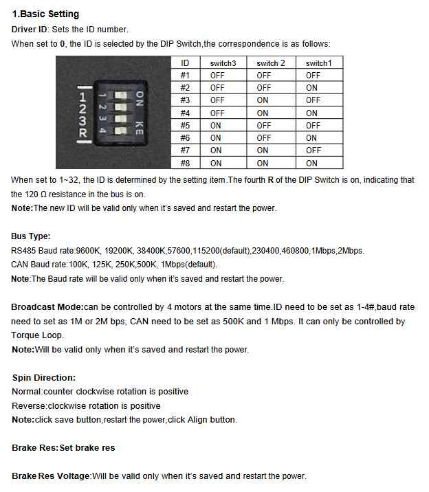
Basic Settings
Driver ID: 1-32 (or dial 1-8)
Bus type: RS485/CAN
RS485 baud rate: 9600~2Mbps (default 115200)
CAN baud rate: 125K~1Mbps (default 1Mbps)
Rotation direction, brake resistance, broadcasting mode (up to 4-axis synchronization)
protection settings
Motor over temperature protection
Drive overheating
Undervoltage/Overvoltage Protection
Protection against overcurrent, short circuit, locked rotor, and signal loss
Limit setting
Maximum angle: ± 359999.99 °
Maximum speed: 0-72000dps
Maximum acceleration, maximum torque current (0-2000)
PID parameters
Angle ring: Kp/Ki
Speed loop: Kp/Ki
Current (torque) loop: Kp/Ki
encoder calibration
Number of motor poles, encoder type, offset
Reduction ratio and zero point setting
Align calibration: automatic calibration of motor forward and reverse rotation
Firmware update
Read hardware/firmware version
Write the corresponding. bin firmware
Automatic calibration after upgrade
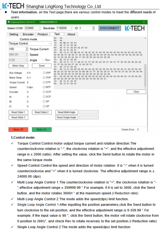
Control mode
Torque control: Output ± 2000 proportional current
Speed control: ± 24000 dps
position control
Single lap: 0-359.99 °
Multi circle: ± 359999.99 °
Incremental angle: relative motion
Status and faults
Bus voltage, motor temperature, real-time current, speed, encoder value
Fault code:
UVP undervoltage
OVP overvoltage
MTP motor overheating
OCP overcurrent
SCP short circuit
SP blockage
LIP signal loss
Key questions and answers
Question 1: What are the core hardware advantages and electrical upper limits of MGv2 servo?
Answer: The core advantage is the integrated gearbox+small backlash+dual encoders+FOC vector control, designed specifically for foot/exoskeleton. Electrical upper limit: 12-60V power supply, rated 10A, peak 20A (10 seconds), 18 bit encoder, 32KHz torque loop, supporting high-precision control with three closed loops.
Question 2: What wiring and configuration rules must be followed for bus communication (RS485/CAN)?
answer:
Both ends of the bus must be connected to a 120 Ω terminal resistor;
RS485 default baud rate 115200, CAN default 1Mbps;
Driver ID supports 1-32, with a maximum of 8 dialing codes supported;
The broadcast mode only supports torque control, with ID set to 1-4 and baud rate ≥ 500K.
Question 3: What are the functions and operational points of encoder alignment calibration?
Answer: Function: To achieve phase alignment between the motor and encoder, ensuring smooth torque and accurate positioning. main points:
Calibration under no-load conditions;
Confirm that the number of motor poles is correct;
The default calibration power is sufficient, and it can be increased appropriately when overloaded;
After calibration, the parameters will be automatically saved and need to be powered on again to take effect.