Automate Direct DL06 Micro PLC
The first volume user manual (third edition Rev. D) of the Automation Direct DL06 micro PLC introduces the hardware specifications, installation and wiring specifications, CPU operating mechanism, memory mapping, high-speed I/O, and basic programming architecture of 9 models. It supports 20 inputs/16 outputs, dual serial communication, 229 instructions, PID closed-loop and RLLPLUS stage programming, meets Class 1 Div.2 explosion-proof and UL/CE certification, and is designed for logic control and motion control scenarios of small automation equipment.
Hardware core specifications
Project parameters
Local I/O 20 inputs (X0~X23), 16 outputs (Y0~Y17), octal addressing
229 instructions (Boolean, Math, PID, High Speed I/O)
Program memory 14.8K words (7.6K ladder diagram+7.6K V memory)
Scanning speed Boolean instruction<0.6 μ s, 1K steps approximately 1-2ms
Communication port Port1 (RS232 9600 fixed); Port2 (multi protocol, 300~38400bps)
Working temperature 0~55 ℃, humidity 5~95%, no condensation
Certified UL, CE, cUL, Class 1 Division 2
Installation and wiring specifications
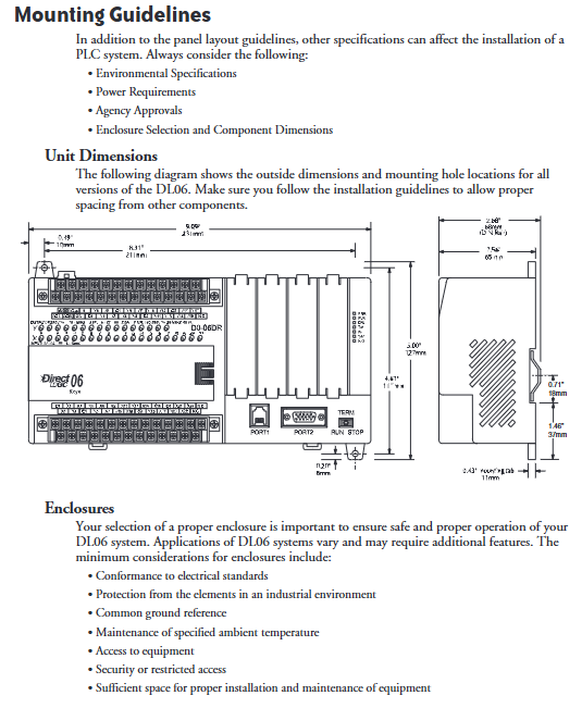
Installation requirements
Method: DIN rail 35mm, horizontal installation
Spacing: Up and down ≥ 30mm, left and right ≥ 20mm
Grounding: Single point common grounding, shielded wire double ended grounding
Wiring rules
Wire gauge: 16~22AWG, single end ≤ 2 pieces
Protection: There is no built-in fuse in the output, it is recommended to add an external fast fuse
Inductive load: DC coil with parallel freewheeling diode, AC coil with MOV/TVS
I/O type
Input: DC input supports drain/source type, AC input 80~132VAC
Output: Relay (2A/point), transistor (0.5~1A/point), AC thyristor (0.5A/point)
CPU and system operation
work mode
RUN: Execute program, refresh I/O
STOP: Stop output, prohibit program changes
TERM: Allow programming/monitoring/mode switching
scanning process
Power on initialization → Read input → Peripheral service → Program execution → PID operation → Write output → Diagnosis
power-down retention
Supercapacitors: hold for several hours
Optional battery D2-BAT-1: Keep for 5 years
Default hold area: C1000~C1777, V400~V37777, CTO~CT177
Diagnostic protection
Watchdog: default 200ms, timeout shutdown
Status LED: PWR/RAN/CPU/Communication Transmission and Reception Status
Error code: stored in V7750~V7757, supports historical queries
Memory Mapping and Resources
Addressing rule: All use octal, no 8 or 9 digits
core resources
Control relay (C): 1024 points
Timer (T): 256 pieces
Counter (CT): 128 pieces
Stage (S): 1024 (RLLPLUS)
Special relays (SP): 512 pieces
V Memory: 7616 words, user available 7488 words, 128 words non-volatile
High speed I/O (HSIO) 6 modes
Mode 10: High speed counter (up to 7kHz)
Mode 20: A/B phase orthogonal counter
Mode 30: Pulse output (up to 10kHz, driving step)
Mode 40: External/Timer Interrupt
Mode 50: Pulse capture (minimum 70 μ s)
Mode60: Adjustable input filtering
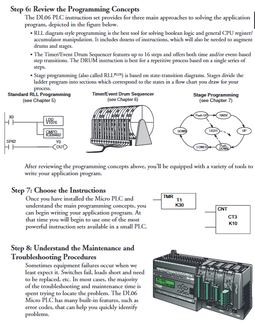
Programming Architecture
Standard RLL: ladder logic, Boolean/Math/Table instructions
DRUM sequencer: 16 step sequential control, triggered by time/events
RLLPLUS Stage Programming: State Machine Process, Suitable for Sequential Actions
Communication Protocol
Port 1: K-sequence, DirectNET, MODBUS RTU (slave only)
Port 2: Supports master/slave stations, supports MRX/MWX commands for reading and writing network data
Key issues
Question 1: How are the 9 models of DL06 divided by I/O type? What are the core advantages of DC models compared to AC models?
Answer: There are 9 types based on input (AC/DC), output (relay/transistor/AC), and power supply (AC/DC). The DC input model supports high-speed I/O (counter/pulse output/interrupt), with a response time of up to 70 μ s, and can be used for simple motion control; The AC model does not have high-speed function and is only suitable for high voltage scenarios.
Question 2: How is the I/O response time of DL06 calculated? How to achieve the fastest response?
Answer: Standard response=input delay+scan time+output delay; The fastest achievable input delay+instruction execution time. Implement the fastest immediate I/O command, disable X0~X3 input filtering, use high-speed I/O mode, and avoid waiting for scan cycles.
Question 3: How to configure the power-off maintenance of DL06? Which regions are kept by default?
Answer: Maintain the range through AUX57 or software settings. Default hold: Control relays C1000~C1777, V memory V400~V37777, counters CT0~CT177; The timer and stage are not maintained by default. Long term maintenance requires the installation of D2-BAT-1 batteries.