Mitsubishi A171SCPU Motion Controller
Product core positioning
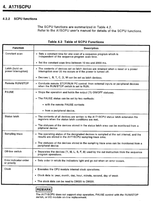
A171SCPU is a Mitsubishi motion controller that integrates sequential control and servo control. It can control up to 4 axes in a single module and is compatible with MELSECNET networking. It is suitable for positioning control in automated production lines.
Core performance parameters
Key values of parameter items
Maximum number of control axes: 4 axes
The total number of I/O points is 256
Memory capacity 32KB
Working temperature 0~55 ℃
Environmental humidity ≤ 80% RH (no condensation)
Altitude ≤ 1000m
Supply voltage 100/200VAC, 50/60Hz
Motion Net cable total length ≤ 30m
Expansion cable total length ≤ 3m
Safety operation standards
Electric shock prevention
It is strictly prohibited to open the casing and terminal cover during power on/operation
After power failure, wait for at least 10 minutes and conduct a power test before proceeding with the operation
Class3 must be independently grounded, and shared grounding is prohibited
fire prevention
The equipment is installed on non combustible materials
Immediately cut off the servo power supply in case of malfunction
Regenerative resistors need to be equipped with overheat protection
Prevent injury
Servo heat sink and resistor are hot, and they still feel hot to the touch for a short time after power failure
Power must be disconnected before touching the motor shaft
Do not approach the equipment during trial operation/demonstration
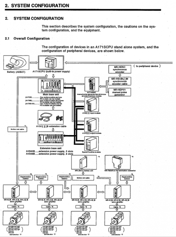
System configuration plan
Basic Configuration
Main frame: A172B, A178B (S1)
Expansion rack: A1S65B (5 slots), A1S68B (8 slots)
Supporting modules: A1S series I/O, special function modules
Servo matching
Driver: MR-H-B/MR-J-B/MR-J2-B
End processing: Connect terminal resistors (MR-TM/MR-A-TM); Absolute value system connected to battery unit (MR-JBAT)
Peripheral Connection
Programming: IBM PC (PC-DOS V5.0 and above)
Control: manual pulse generator (MR-HDP01), synchronous encoder
Communication: RS-232C, RS-422 conversion
Installation and wiring requirements
Install
Reserve ventilation spacing of * * ≥ 30mm * * above the module
The distance between the left and right sides and the surrounding equipment is ≥ 50mm**
The inner spacing of the panel is ≥ 100mm**
Support TH35 series DIN rail installation
wiring
Separate wiring for power and signal lines, with a spacing of ≥ 100mm
Shielded twisted pair cables for encoder lines, with the shielding layer grounded at one end
Terminal screw torque: 59~88N · cm
Prohibit parallel connection of multiple power modules for 24VDC output
Debugging and Running
OS installation
Turn on the Install switch (SW1-1 ON)
After writing to the OS, turn off the switch and restart to take effect
Trial operation process
Check wiring → Set axis number → Parameter configuration → Program writing → JOG testing → Return to origin → Automatic operation verification
Key Settings
I/O Control: Refresh/Direct Mode (SW302-1 Switching)
Memory protection: SW302-2 on/off
Voltage selection: 100V short-circuit jumper, 200V open circuit
Maintenance and upkeep
routine inspection
POWER/RUN/ERROR indicator light status
Module fixation and terminal screw fastening
Regular inspection (6-12 months)
Environmental temperature and humidity, dust/corrosive gases
Battery voltage, connector connection status
Battery replacement
Built in battery: Model A6BAT, with a lifespan of approximately 1 year
Replacement deadline: Completed within 5 minutes after power failure
Absolute value battery: MR-JBAT, with a lifespan of 5 years
Fault diagnosis and handling
Indicator light failure
POWER not lit: power supply, module installation, overcurrent/overvoltage protection
RUN not lit: program error, remote stop, noise interference
ERROR on: Hardware malfunction, parameter error, WDT timeout
Common error codes
11: Parameter error
23: WDT error (scan time too long)
31: I/O module malfunction
40: Control bus error
I/O fault handling
Input not OFF: leakage current, parallel 1k Ω/0.5W resistor
Output not functioning: power supply, load, wiring, module damaged
Appendix Key Information
Servo matching: Clarify the correspondence between MR-H-B/J-B/J2-B and various series of motors
Cable specifications: Motion Net, encoder cable model, length, wiring definition
Braking characteristics: Calculation formula for stopping distance of dynamic braking and electromagnetic braking
Dimensions: Installation dimensions for CPU, module, rack, and battery unit
Key questions and answers
Question 1: What are the system core limiting parameters of A171SCPU and why must they be followed?
Answer: The core limitations include a maximum 4-axis control, 256 total I/O points, Motion Net cable length ≤ 30m, operating temperature range of 0-55 ℃, and independent Class3 grounding. Reason for compliance: Exceeding the number of axes/I/O points will result in control failure; Excessive cable length can cause signal attenuation and interference; Overheating can accelerate component aging; Improper grounding can cause electric shock and electromagnetic interference, directly affecting system safety and positioning accuracy.
Question 2: What are the mandatory requirements for safety grounding and wiring of A171SCPU, and what are the consequences of violating them?
Answer: Mandatory requirement: ① Adopt Class3 independent grounding and prohibit sharing grounding with other devices; ② Separate the wiring of power lines, power lines, and signal lines with a spacing of ≥ 100mm; ③ Use shielded twisted pair cables for encoders and communication lines, with the shielding layer grounded at one end; ④ The tightening torque of the terminal screw is 59~88N · cm. Violation consequences: Poor grounding leads to the risk of electric shock, signal interference causes positioning errors; Mixed wiring leads to noise interference and equipment misoperation; Loose screws lead to poor contact, overheating, and burning.
Question 3: What are the key steps and precautions for replacing the A171SCPU battery, and what are the effects of exceeding the time limit?
Answer: Key steps: ① Turn off the power of the controller; ② Remove the old battery (A6BAT) within 5 minutes; ③ Insert a new battery and connect the leads; ④ Restart the verification program and parameters. Attention: ① The battery life is about 1 year. If BATTERY ERROR occurs, replace it immediately; ② Do not short-circuit, disassemble, or heat the battery; ③ The absolute value system requires replacement of the MR-JBAT battery. Timeout impact: If the power is cut off for more than 5 minutes, the program, parameters, and absolute value position data will be lost, causing the system to fail to start and locate normally.