MITSUBISHI MDS-A/B Series CNC AC Servo/Spindle System
The official specification manual for Mitsubishi MDS-A/B series CNC AC servo/spindle system (BNP B3759B) fully covers the MDS-A/B CV/CR power unit, MDS-A/B Vx servo drive, MDS-A/B SP spindle drive, and supporting HA series servo motors. It clarifies safety specifications, system architecture, hardware wiring, parameter settings, capacity selection, heat dissipation, and alarm processes, supports two power supply schemes: power regeneration and resistance regeneration, and is compatible with MELDAS M500 series NC. It provides 0.05-15kW full power range servo and 0.4-30kW spindle drive, with IPM integration, high response control, and dual safety emergency stop, suitable for high-precision feed and spindle control of CNC machine tools.
Safety regulations (mandatory requirement)
Core security level
DANGER: Death/serious injury caused by misoperation
Warning: Protection against electric shock and fire
CAUTION: Prevent injury and equipment damage
Key safety clauses
Wait for 10 minutes after power failure before operation to prevent electric shock caused by residual electricity
The drive and motor must be grounded at level 3 or above
Installed on non combustible materials, do not approach combustible materials
The emergency stop circuit adopts dual protection of NC emergency stop and external emergency stop
Electric brake is only used for holding and cannot be used for conventional braking
Overall system architecture
MDS-A/B adopts a centralized rectification and distributed drive architecture:
Power supply unit: Convert three-phase AC to DC bus to supply power to all drives
Servo drive: control servo feed axis
Spindle drive: controls spindle rotation, positioning, and C-axis
Battery Unit: Achieving Absolute Value Encoder Position Maintenance
List of Unit Models
table
Unit type, model series, power range
Power regeneration power supply MDS-A/B-CV 3.7-37kW
Resistive Regenerative Power Supply MDS-A-CR 1.0-9.0kW
Single axis servo drive MDS-A/B-V1 0.1-15kW
Dual axis servo drive MDS-A/B-V2 0.1 × 2-4.5 × 2kW
Spindle drive MDS-A/B-SP 0.4-30kW
Power Supply Unit (CV/CR)
1. MDS-A/B-CV (power regeneration type)
Advantages: Braking energy feedback to the power grid, low heating
Input: Three phase 200V 50/60Hz
Output: DC 270-311V
Features: IPM module, external emergency stop input, LED status display
Mandatory requirement: B-CV-370 must have an external contactor connected
2. MDS-A-CR (Resistance Regenerative Type)
Advantages: Low cost, no need for reactors
Control power supply: DC24V
External regeneration resistor unit must be connected
No energy feedback, heat is dissipated through resistors
Servo system (V1/V2+HA motor)
1. Servo drive
V1: Single axis, compact, high dynamic
V2: Dual axis, saving space and reducing costs
Control mode: Current loop → Speed loop → Position loop Three loop control
Standard configuration: 100000 pulse/encoder, nanometer level instructions
2. HA series servo motor (core specifications)
Motor series power range rated speed features
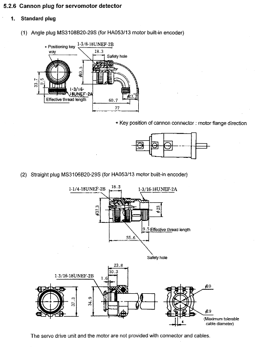
HA053/13 0.05-0.1kW 3000rpm Ultra small capacity, high response
HA23/33/43/83 0.3 – 1kW 3000rpm Small Universal
HA103/203/303 2-4.5kW 3000rpm medium-sized machine tool
HA703/903 7-9kW 2000rpm heavy cutting
HA-LH11K2/15K2 11-15kW 2000rpm high power, high torque
Spindle System (SP)
Power: 0.4-30kW
Function: Speed control, positioning (M19), C-axis, rigid tapping
Supporting encoders: Magnosensor, OSE90K, MBE90K, MHE90K
Interface: CN5 (temperature), CN6 (positioning), CN7 (C-axis)
Wiring and layout specifications
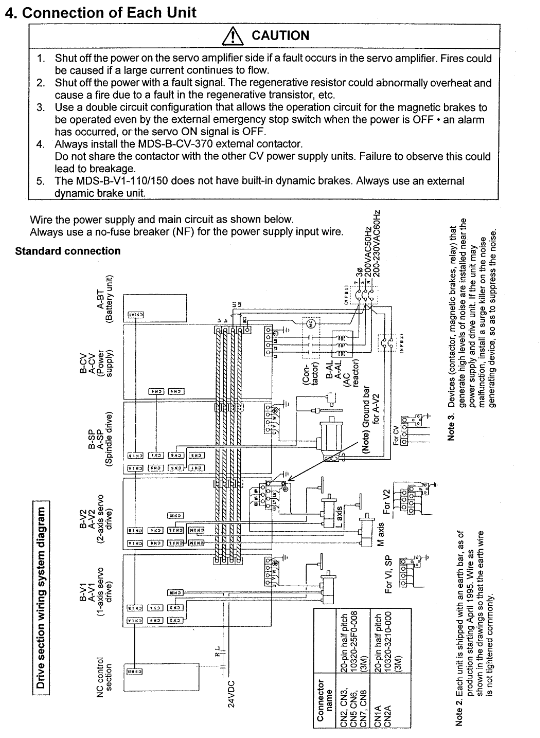
1. Definition of Core Wiring
L1/L2/L3: Three phase main power input
L+/L —: DC bus, connecting all drives
L11/L21: Control power input
U/V/W: Drive output to motor
PE: Protective Grounding
2. Layout mandatory rules
Spindle drive, 11kW and above servo must be located adjacent to the power supply unit
Multiple power supply units L+/L independent connection, prohibit common bus
Each power supply must be equipped with an AC reactor
Separate wiring for power and signal lines
Capacity and cable selection
1. Formula for calculating power capacity
Single servo axis: power>total spindle power+servo power
Multiple servo axes: power>total spindle power+0.7 x total servo power
2. Cable selection (core)
Specification of the main power cord in the power range
≤7.5kW IV2SQ
11–18.5kW IV3.5SQ/5.5SQ
22–30kW IV14SQ/22SQ
37kW IV38SQ/50SQ
Alarm and Diagnosis
1. Status display
7-segment LED display: initialization, ready, servo ON, alarm
Charging light: On indicates that the busbar is live, and disassembly is prohibited
2. Typical alarms
61: Power module overcurrent
63: Regeneration fault
67: Lack of phase
73: Over regeneration/overvoltage
74: Regenerated resistor overheating
Key issues
Question 1: What is the core difference between MDS-B-CV and MDS-A-CR power units, and what scenarios are they applicable to?
answer:
MDS-B-CV (power regeneration): energy feedback to the grid, low heat generation, high efficiency, high cost, requires AC reactors, suitable for continuous braking, multi axis, high-power, energy-saving machine tools.
MDS-A-CR (Resistance Regeneration): Energy is consumed through heat, with low cost and no need for reactors. It requires an external resistor and is suitable for light braking, low power, and simple equipment.
Question 2: How are HA servo motors classified by power and inertia, and what processing scenarios correspond to different models?
answer:
Low power and low inertia (HA053/13/23/33): 0.05-0.54kW, 3000rpm, suitable for light load, high speed, high-precision flying cutting/milling.
Medium power universal (HA103/203/303): 2-4.5kW, 3000rpm, suitable for molds, parts, and universal milling.
High power heavy cutting (HA703/903/LH11K2/15K2): 7-15kW, 2000rpm, suitable for heavy cutting, gantry, and machining centers.
Question 3: What are the mandatory requirements for L+/L bus and emergency stop circuit in system wiring, and what are the consequences of violating them?
answer:
L+/L —: Multiple power units must be connected independently, and short circuits on the common bus are prohibited, otherwise it may cause the machine to explode and burn out the module.
Emergency stop: It must have a dual circuit of NC emergency stop and external emergency stop. B-CV-370 must be connected to an external contactor, otherwise it will not meet safety standards and cannot pass CE.
When the charging light is on, it is absolutely forbidden to disassemble or assemble it, otherwise it may cause electric shock and damage to the drive.