Eaton Cutler Hammer Pull SPB Automatic Transfer Switch (ATS) Operation and Maintenance
The Eaton Cutler Hammer Pull SPB Automatic Transfer Switch (ATS) Operation and Maintenance Manual (IB01602003E) covers rated currents of 600-4000A and includes automatic, bypass isolation, closed transition/open transition structures. It specifies the entire process of safety warnings, equipment structure, installation wiring, pull mechanism operation, bypass switching, troubleshooting, and regular maintenance, emphasizing mechanical/electrical interlocking, energy storage operation, 5 position states, UL1008 certification, and is suitable for emergency/backup power supply uninterruptible power supply scenarios.
Product type and configuration
1. Switch type
Type description
Automatic transfer switch for monitoring dual power supply and automatic switching
Uninterrupted power supply during bypass isolation maintenance
Non automatic electric manual trigger, electric operation
Basic power panel type without logic, external control system
2. Switching method
Open Transition: First disconnect and then close to prevent parallel power supply
Closed Transition: Close first and then disconnect, zero interruption power supply
3. Key parameters
Switching speed:<5 cycles
Polarity: 2P/3P/4P
Voltage: 208-600VAC
Tolerant capacity: maximum 100kA@480V
Structural composition
Power panel
Main contact: Insulated shell switch/circuit breaker
Conversion mechanism: energy storage spring operation
Pulling mechanism: allows power-off maintenance
Voltage selection panel
7-speed tap: 208-600V adaptive
Logic panel
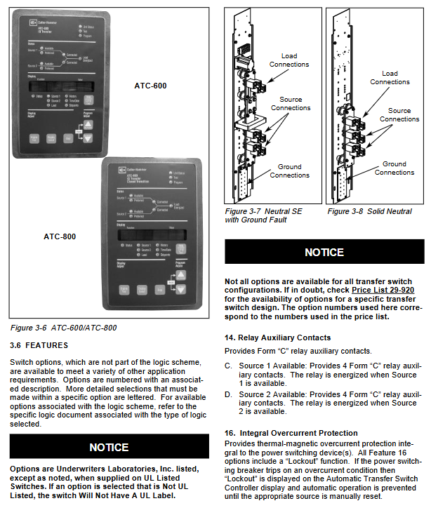
ATC-600 (open circuit)/ATC-800 (closed circuit)
Cabinet type
|NEMA | Protective Application|
|1 | Indoor universal|
|3R | Outdoor Rainproof|
|4/4X | Dustproof, waterproof, and corrosion-resistant|
|12 | Dust and drip proof|
Installation and wiring
Installation requirements
Load bearing foundation, dry and ventilated environment
Seismic installation: 1/2-13 UNC bolts, torque 50ft lbs
Cable specifications
|Switching current | Number of cables per phase | Line gauge range|
| 800–2000A | 6–8 | 4/0–500MCM |
| 2500–3000A | 9–12 | 4/0–750MCM |
| 4000A | 12–16 | 4/0–750MCM |
Key points of wiring
Power off operation is required
The terminal torque meets the standard, and direct connection with bare wires is prohibited
Engine start signal terminal 51/52
Pull mechanism operation
4 positions
CONNECT: Normal operation
TEST: Secondary connection, primary disconnection
DISCONNECT: Completely disconnected
WITHDRAW: can be extracted for maintenance
Security interlock
The switch must be opened before it can be pulled
Can only be closed on CONNECT/TEST/DISCONNECT
Bypass isolation operation
Purpose: To maintain uninterrupted power supply for switch loads
Process: Bypass closing → Work switch opening and extraction → Maintenance → Reset → Bypass opening
Key: Key interlock to prevent accidental alignment
Troubleshooting
Completely inactive
Check the main voltage, logic plugin, voltage tap, and energy storage mechanism
Do not automatically switch back to mains power
Check the mains voltage, emergency opening coil, closing coil, and wiring
Non automatic tangential emergency response
Check the emergency voltage, mains opening coil, and emergency closing coil
Cannot automatically store energy
Check the energy storage motor power supply A6/A2 and the motor body
Maintain standards
Regular projects
Power off cleaning, terminal tightening, insulation inspection, action testing, filter replacement
Disassembly and assembly of cover plate
NEMA 1:3/8 “wrench, tighten screws to 8ft lbs
NEMA 3R: with sealing gasket, special handle for disassembly and assembly
vulnerable parts
Air filter: TSAFDO
Padlock handle: TSDHPZFS
Key issues
Question 1: What are the four positions of the pull-out switch? What are their respective functions?
answer:
CONNECT: fully connected, normal power supply operation
TEST: Connect the secondary circuit and disconnect the main circuit, used for debugging
DISCONNECT: Primary/secondary completely disconnected, security check
WITHDRAW: The cabinet can be removed for maintenance and replacement
Question 2: What is the core difference between an open transition switch and a closed transition switch? What scenarios are applicable to each?
answer:
Open circuit transition: first open circuit and then close circuit, strictly prohibit parallel operation of dual power sources, applicable to ordinary backup power sources
Closing transition: Close the switch first and then open it, providing zero interruption power supply, suitable for critical loads such as hospitals and data centers that do not allow power outages
Question 3: What is the core value of bypass isolation type transfer switch? What are the standard switching steps?
answer:
Core value: Continuous power supply to the load without interruption during the maintenance of the conversion switch.
Standard steps:
Turn the generator switch to OFF/RUN to prevent accidental start-up
Unlock the bypass switch with the key and close it
Open the switch and pull out the working switch
After completing maintenance, push back the work switch and automatically close it
Open bypass switch, restore automatic mode