FANUC I/O Unit MODEL A Connection and Maintenance
Basic Information
Name: FANUC I/O Unit MODEL A CONNECTION AND MAINTENANCE MANUAL
Applicable equipment: FANUC I/O Unit MODEL A series I/O unit
Compatible with CNC: 0i, 15i, 16i, 18i, 30i/31i/32i/35i, Power Mate i, Power Motion i
Core purpose: To guide the installation, wiring, configuration, debugging, maintenance, and troubleshooting of I/O units
Document structure: Safety instructions → Connection section → Maintenance section → Appendix
Safety regulations (mandatory requirement)
Installation/wiring/maintenance must be powered off to prevent electric shock and equipment damage
It must be reliably grounded and follow the grounding standards of various countries
Do not plug or unplug modules or touch terminals while they are live, to prevent static electricity and high temperature burns
Overloading the output module can easily cause a fire, and an external fuse needs to be configured
Prohibited for use in personal safety related scenarios, external safety circuits must be configured
System architecture and communication
(1) Communication bus
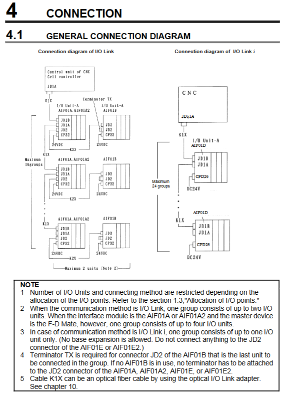
I/O Link: Traditional bus, maximum 1024 DI/DO points per channel, 16 groups
I/O Link i: High speed bus, maximum 2048 DI/DO points per channel, 24 groups
Main station: CNC; Slave: I/O Unit MODEL A
Support long-distance transmission and anti-interference of fiber optic adapters
(2) System topology
1: 1: 1: n, n: 1, n: m flexible networking
Supports base expansion (I/O Link), I/O Link i does not support expansion
Up to 2 units per group (I/O Link), I/O Link i only has 1 unit per group
Hardware composition
Base unit
ABU05A/B: 5 slot horizontal/vertical
ABU10A/B: 10 slot horizontal/vertical
Interface module (core)
AIF01A/A2: Dedicated for I/O Link
AIF01D: I/O Link i Dedicated
AIF01E/E2: Dual protocol compatibility
AIF02C: Supports both Model A/B simultaneously
I/O module
Digital input/output: 16 point, 32 point, 24VDC
Analog input/output: 12 bit, 14 bit, 16 bit
High speed counting module: ACT01A
Temperature input module, relay output, AC output module
Installation specifications
Environmental requirements: 0~55 ℃, humidity ≤ 75%, dustproof and anti cooling liquid
Installation direction: Vertical installation is beneficial for heat dissipation, with a spacing of ≥ 100mm above and below
UL/CSA certification: Pollution level 2 environment, using AWG16 and above power cords
Heat dissipation: Natural convection is required for module heating, and placing heating devices below is prohibited
Electrical connection (core engineering part)
(1) Power supply
Power supply: 24VDC ± 10%
Wiring sequence: First connect the CNC power supply, then connect the I/O unit power supply
Power calculation: Configure power capacity based on the total current of the module
(2) Grounding
Protective grounding: Base specific grounding terminal, wire diameter ≥ 2mm ²
Shielding grounding: Single ended grounding of analog/communication lines to suppress noise
(3) Communication cable
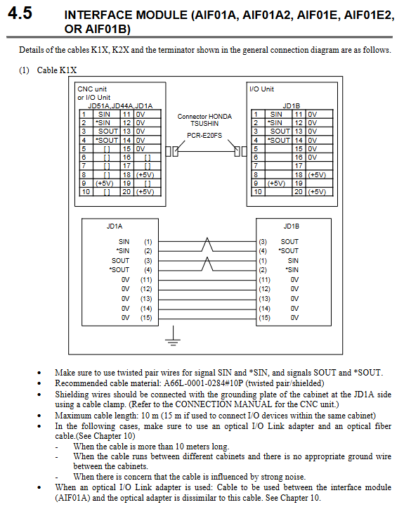
K1X/K2X: shielded twisted pair wire, maximum length 10m
Terminal resistance: The end of the group must be connected to TX terminal (A03B-0807-K806)
Fiber optic communication: used for long-distance and strong interference environments
(4) I/O wiring
Digital quantity: POS/NEG, distinguish common end
Analog quantity: voltage ± 10V, current ± 20mA, twisted pair shielded wire
Relay output: Inductive loads must be connected in parallel with freewheeling diodes/surge absorbers
Module specification details
(1) Digital input module
Voltage: 24VDC, response time 2ms/20ms
Type: Isolated/Non Isolated, Common Anode/Common Cathode
Features: AID16DM/LM with common terminal voltage monitoring and abnormal alarm
(2) Digital output module
Type: transistor, relay, AC thyristor
Protection: overcurrent, over temperature, short circuit protection, alarm LED indication
Specification: 0.3A~2A/point, with reduced capacity curve
(3) Analog module
AAD04A: 12 bits, 4 channels, ± 10V/± 20mA
AAD04B/B2:16 bit high-precision, high-speed sampling
ADA02A/B: 12/14 bit output, ± 10V~0~20mA
(4) High speed counting module (ACT01A)
Count: 1 channel, up to 500kHz
Mode: A/B phase, positive and negative pulse modes
Function: Compare output, tag synchronization, external start stop, alarm diagnosis
Address allocation rules
I/O points are occupied in segments of 32/64/128/256 points
Maximum per group: I/O Link=256 points; I/O Link i=512 points
The analog/high-speed counting module occupies a fixed byte address
Special modules (monitoring/protection) occupy additional DI/DO addresses
Maintenance and fault diagnosis
(1) Status indicator light
PWR: Power supply is normal
LNK: Communication is normal
ER/ALM: Fault alarm
Module LED: Channel status, alarm indication
(2) Troubleshooting
Communication failure: Check the terminal, cable, station number, and baud rate
Output fault: Check load, fuse, protection action
Analog fault: Check wiring, shielding, grounding, and range
Counting fault: Check the encoder type, phase, and wiring
(3) Daily maintenance
Regularly clean dust and coolant
Check terminal fastening and cable damage
Regular replacement of fuses, relays, and filters