Lenze 8200 Vector Series Vector Inverter
Basic Information
Product Series: Lenze 8200 Vector Inverter
Power range: 0.25 kW… 90.0 kW
voltage level
Single phase/Three phase 230V
Three phase 400 V/500 V
Purpose: Selection, configuration, installation, wiring, module matching, accessory selection
Core positioning: modular, high usability, industrial vector control frequency converter
Core structure
Product information: Model code, abbreviation, selection guide
Host controller: specifications, power, installation, size, special design
Automation module: operation panel I/O、 Bus, PLC module
Attachment: Incoming reactor, filter, braking resistor, motor filter, fuse
Application Cases
service
Product Information (Core: Selection)
1. Model coding rules (E82EVxxxKxx)
82:8200 series
V: Vector control
Power: 25=0.25kW, 75=0.75kW, 152=1.5kW
Voltage: 2=230V, 4=400V
Structure: C=standard, B=high power, 200=no built-in filter, C=with built-in filter
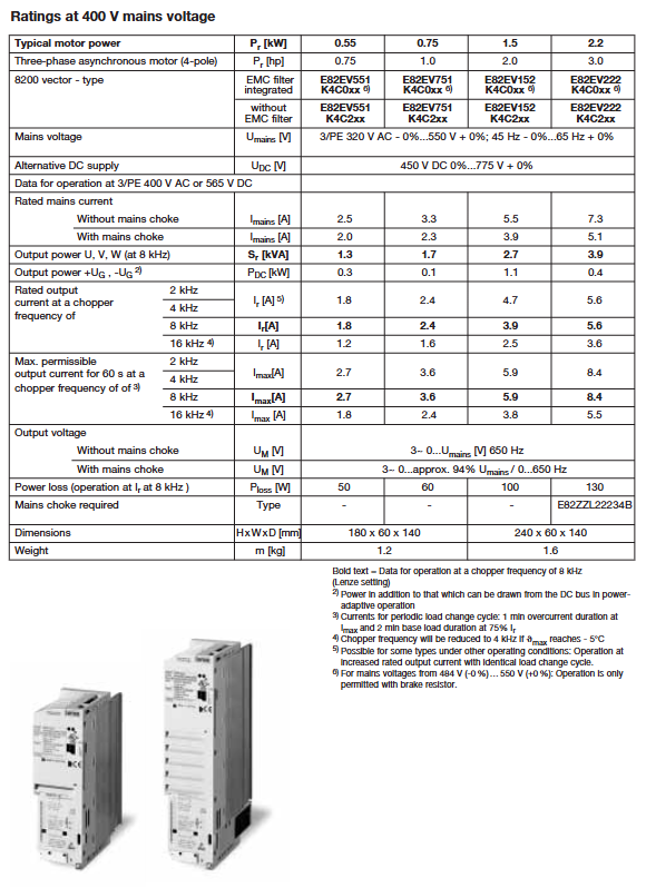
2. Quick selection table (most important)
Divided into a large number of tables based on voltage, power, whether equipped with EMC filters, and rated/increased capacity operation, directly matched:
Host model (such as E82EV751K4C200)
Standard I/O module (E82ZAFSC010)
line reactor
RFI filter
braking resistor
Supports two operating modes:
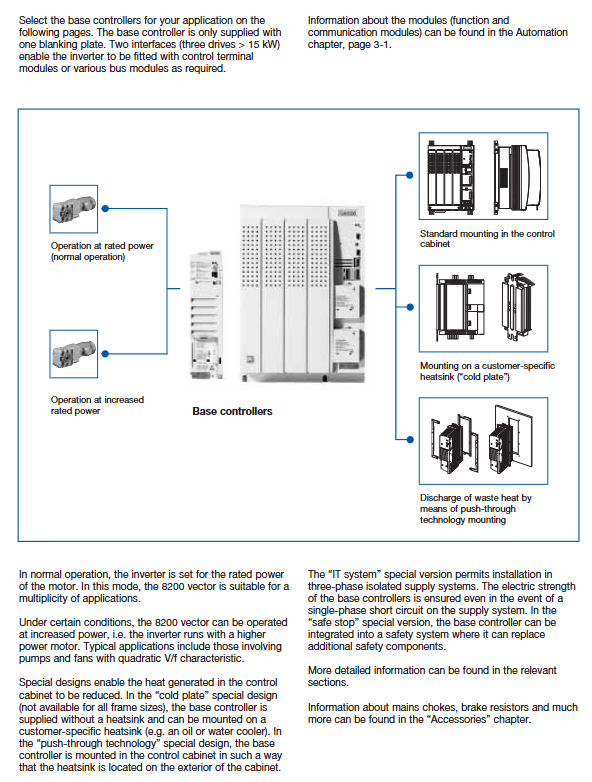
Rated power operation (Normal): standard load
Increased rated power operation: Variable torque for fans and pumps, capable of carrying larger motors
Base controllers
1. Technical parameters (general)
Control methods: V/f linear/square, vector control, sensorless torque control
Carrier frequency: 1/2/4/8/16 kHz
Output frequency: 0… 650 Hz
Overload: 180% × 60s; 210% × 3s above 15kW
Protection: overcurrent, overvoltage/undervoltage, overload, overheating, ground fault, motor PTC protection
Environment: -10…+55 ℃, altitude 0… 4000m (reduced capacity)
Certification: CE, UL, cUL, EN 55011 A/B level
2. Basic I/O configuration
Analog quantity: 2 inputs/2 outputs (0-10V/0/4-20mA)
Digital quantity: 6 inputs/2 outputs+relay output
Frequency input: up to 100kHz
Encoder interface: optional
3. Installation method
Installation inside standard cabinet
Side by side installation (only requiring a 3mm gap)
Rotating bracket installation (easy to maintain)
DIN rail installation (low power)
Cold plate heat dissipation: no built-in fan, external heat dissipation plate
Push through installation: The radiator extends outside the cabinet to lower the temperature inside the cabinet
4. Special version
Safe Stop: EN 954-1 Cat.3, without contactor
IT Grid Version: Suitable for ungrounded distribution systems
Automation
1. Operation panel
Keypad XT: Text display, parameter copying, password protection
GDC easy software: PC debugging, oscilloscope, parameter management
2. I/O functional module
Standard I/O PT (E82ZAFSC010): standard, spring terminals
Application I/O PT: High order I/O, dual-mode analog, high-speed counting
3. Bus module (full coverage)
CAN / CANopen
PROFIBUS‑DP
INTERBUS / INTERBUS Loop
DeviceNet
LON
LECOM‑AB(RS232/485)
Fiber optic LECOM-LI
AS‑Interface
4. Drive PLC (built-in programmable controller)
IEC 61131-3 Programming
8 inputs/4 outputs, 3 analog inputs, 1 analog output
Built in CAN bus
Scalable counting/analog board
Accessories
1. Cable protection
Fuse, circuit breaker, fuse holder (matched by power)
2. Mains choke
Suppress harmonics, protect the frequency converter, and extend its lifespan
3. RFI/EMC filters
Meets EN 55011 levels A and B
Divided into internal/external, matched according to power and cable length
4. Motor filter
Long cables (>20m) are essential to protect motor insulation
5. Braking unit and braking resistor
0.25… 11kW: Built in braking transistor
Above 15kW: External braking unit
Provide corresponding resistance/power resistance
6. Other
PTC motor protection module
Given potentiometer
Display table, plug, EMC kit