BECKHOFF AM8000/AM8500 Series Synchronous Servo Motor Operation Manual
Product Overview
1. Product positioning and core features
AM8000/AM8500 is a brushless three-phase synchronous servo motor that uses neodymium iron boron permanent magnet rotor, electronic commutation structure, and no slip ring/commutator. It has a long lifespan, high positioning accuracy, and excellent dynamic response, and is widely used in motion control scenarios such as machine tools, robotic arms, and automated production lines.
Core structure: stator three-phase winding, rotor with built-in permanent magnets; Standard LPTC-600 temperature sensor (equivalent to KTY84) for winding overheating protection.
Protection and appearance: The shell is coated with acrylic powder (RAL 7016 charcoal gray); The standard housing is IP65, and the shaft end comes standard with IP54. Installing a shaft sealing ring can achieve IP65.
Installation standard: Following DIN 60034-7, the mainstream installation form is IM B5, supporting IM V1/IM V3 posture.
2. Classification of models across the entire series
According to flange size and power/torque, it is divided into seven series: AM801x~AM807x, AM853x~AM856x. The flange specifications are F1~F7, covering the full power range from small torque to large torque. Different series have differentiated designs in terms of stator pole number, bearing specifications, and external dimensions.
3. Optional configuration (factory pre installed, not available for on-site installation)
Encoder types: Resolver rotary transformer, OCT single/multi turn, Hiperface single/multi turn, resolution and accuracy grading, supporting up to 24 bit SIL2 level encoders.
Maintain brake: 24VDC power-off brake, only used for stopping and holding, strictly prohibited as working brake; Additional mechanical protection/redundant braking is required for the vertical axis.
Axis structure: optical axis, with flat key axis, with shaft sealing ring+sealing gas interface version.
External cooling fan (Fan cover): forced air cooling to increase the continuous output power of the motor and adapt to high load conditions.
Sealed gas interface: connected to stable and clean compressed air (0.1 ± 0.05 bar) to prevent dust and liquid from entering, suitable for harsh working conditions.
4. Encoder accuracy parameters
Encoder type, resolution, system accuracy
Resolver 14bit ±0.17°
Standard OCT/Hiperface 18 bit ± 0.03 °
Advanced OCT (firmware V2.10+) 23 bit ± 0.0125 °
Advanced OCT (SIL2) 24 bit ± 0.0069 °
Environmental, Transportation, and Storage Standards
1. Environmental parameters
Operating temperature: 0 ℃~+40 ℃; When the altitude is greater than 1000m and the environment is greater than 40 ℃, power reduction is required for use.
Transportation/storage temperature: -25 ℃~+70 ℃; Humidity 5%~95%, no condensation.
Environmental level: 2K3 (climate), 1C2 (chemical), 1B2 (biological), resistant to conventional corrosion and dust.
2. Transportation requirements
Use original factory packaging throughout the entire process, avoid severe impact or falling, and avoid impacting the motor shaft and encoder.
Lifting specifications:
AM8x1~AM8x5: can be directly transported;
AM8x6: Use slings to secure only the casing and prohibit hanging shafts;
AM807: The body comes standard with lifting lugs, and only lifting lugs are used to ensure force balance.
Stacking restrictions: There is a clear upper limit for the stacking height of different series of cardboard boxes, and large motors are only allowed to be placed in a single layer.
3. Long term storage
The longest storage period is 2 years, and exceeding this period will cause the lubricating grease to fail.
Conduct routine inspections every 6 months to maintain a dry, vibration free, and sun free environment.
The yellow protective cap on the shaft end must not be removed in advance to prevent damage to the shaft surface and bearings.
Core electrical and mechanical parameters
1. Temperature protection system
Built in LPTC-600 thermal sensor, temperature threshold:
Warning temperature: 120 ℃;
Shutdown protection temperature: 140 ℃;
The manual provides a full temperature range sensor resistance comparison table, which can be used for driver parameter configuration.
2. Power Capacity Reduction Rules
High temperature derating: Reduce the rated torque/current according to the temperature coefficient at an ambient temperature of 40-50 ℃.
Capacity reduction at altitude: Capacity reduction begins at altitudes greater than 1000m, with a 6% reduction at 2000m, a 17% reduction at 3000m, and a 55% reduction at 500m.
When high temperature and high altitude are superimposed, multiply the two coefficients to calculate the actual output.
3. Bearings and shaft loads
The front and rear bearings adopt sealed ball bearings, distinguishing between fixed and floating ends, and each series of bearing models is clear.
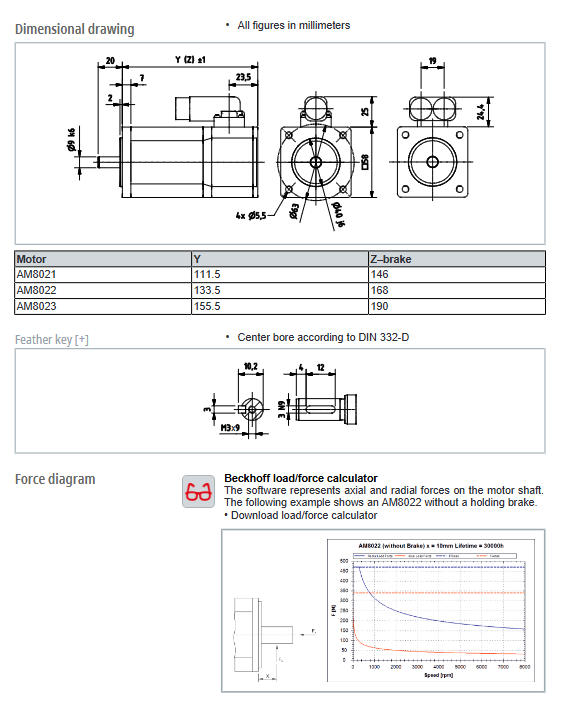
Strictly limit the radial and axial loads on the shaft, and use official load calculation tools to verify the service life for synchronous belt/gearbox applications.
Shaft end structure: Compliant with DIN 748 and DIN 6885 standards, supporting seamless couplings such as expansion sleeves and corrugated pipes.
4. Brake parameters (24VDC)
Power supply range: 24VDC (-10%~+6%);
Different specifications of motors have different brake torque, suction/release delay, and working current;
A single emergency stop has speed and inertia limitations, and frequent emergency stops can accelerate brake wear.
Mechanical installation and disassembly
1. Installation posture and heat dissipation
Standard posture IM B5, supports IM V1/IM V3; IM V3 is prone to fluid accumulation, and should be used with caution in high humidity/water dripping environments.
Reserve ventilation space and prohibit blocking the heat dissipation area; The installation of fan versions requires ensuring smooth air ducts.
2. Flange installation
The flange screws are made of 8.8 grade high-strength bolts, and the corresponding screw specifications and tightening torques for each series are clear and must be strictly followed.
Installation requirements:
Couplings/pulleys must be installed in the center and must not be loaded unevenly, otherwise it may cause vibration and bearing damage;
Hot installed components require temperature control operation and ensure coaxiality after installation.
Disassembly of shaft end accessories: Only use a dedicated puller and do not strike the shaft body.
3. Installation of external fan
The fan is powered by 24VDC, with power and current differentiated by specifications, and comes with dedicated cables.
Accurate installation alignment, compliant screw torque, and regular cleaning of the fan dust screen.
4. General mechanical taboos
Prohibit the shaft from bearing additional forced support to avoid over positioning of the shaft system;
Do not touch rotating parts or high-temperature shells during operation;
The overall vibration and impact of the machine must meet the standards, and exceeding the range may damage the encoder and bearings.
Electrical installation and wiring
1. Connect the system
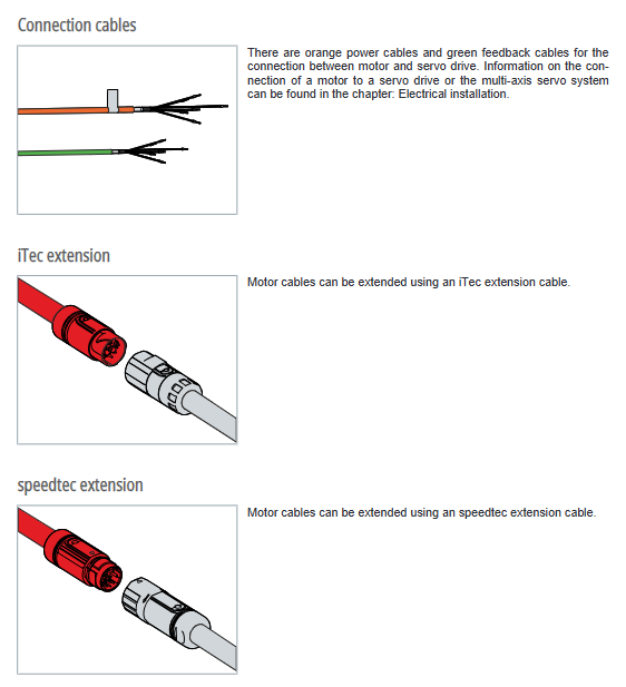
Motor integrated rotatable junction box (maximum rotation of 330 °), providing three types of mainstream connectors:
ITec, Speedtec, M23, M40 interfaces, all with IP65 protection;
Distinguish between power lines, encoder lines, brake lines, and temperature detection lines, and the manual provides complete definitions for each pin.
2. Cable selection
Pre fabricated shielded cables from the original factory must be used. Non standard cables can easily cause EMC interference, communication failures, and loss of warranty.
Select the corresponding cable model based on the drive model (AX5000/AX8000), motor series, and usage scenario (fixed/high dynamic/torsional working conditions), including main line, extension line, and feedback line.
Service life of the connector: ≤ 500 insertions and removals, ≤ 10 rotations of the junction box. It is recommended to replace it if it exceeds the deadline.
3. Wiring specifications
Strictly distinguish between U/V/W three-phase power lines, PE grounding, positive and negative brake, temperature signal, and encoder signal lines.
Grounding requirements: The casing and cable shielding layer should be reliably grounded to meet EMC and anti electric shock requirements.
Sealing requirements: The sealing ring of the junction box should be intact, and the waterproof and dustproof structure should not be damaged.
Debugging, operation, and daily maintenance
1. Power on debugging process
Pre commissioning inspection: Mechanical installation, wiring, grounding, brake, and fan are all intact.
Step by step debugging: Single axis individual testing → Check steering, noise, temperature rise → Linkage debugging.
Software configuration: Use TwinCAT DriveManager to complete motor model identification, parameter configuration, and axis function setting.
2. Key points of operation inspection
Regular inspection during operation: abnormal noise, abnormal noise, temperature rise, vibration, cable aging, fan condition, brake status.
3. Cleaning standards
Clean after power outage, do not soak or rinse with high-pressure water gun.
Explicitly allow/prohibit cleaning agents: dilute acids, salts, and some organic solvents can be used; It is strictly prohibited to use strong corrosive media such as bleach, concentrated hydrochloric acid, bromide, etc.
4. Regular maintenance cycle
Component maintenance cycle maintenance content
Ball bearings replaced after 30000 operating hours
Complete machine inspection for 2500 hours/annual inspection for bearing abnormal noise and temperature rise
5000 hour visual inspection of the shaft seal ring and replacement of lubricating grease as needed
Power/feedback cable 5 million bending cycle replacement
Clean and check the dynamic balance of fan components every six months
Replace if the wiring connector is damaged after 500 insertions and removals
Fault diagnosis and handling
The manual categorizes faults based on their symptoms, summarizes typical problems, causes, and solutions. The core common faults are as follows:
Motor cannot start: driver not enabled, brake not released, mechanical jamming, phase loss/wiring error.
Operation stuttering and abnormal noise: poor cable shielding, improper driver parameters, damaged bearings, and foreign objects entering.
Abnormal high temperature: excessive load, poor heat dissipation, environment/altitude exceeding specifications, temperature sensor malfunction.
Brake failure: abnormal power supply to the brake, cable short circuit, and damage to the brake body.
Encoder error: broken feedback line/loose connector, encoder hardware malfunction.
Leakage/short circuit: power line damage, insulation aging.
For all hardware malfunctions, it is recommended to contact Beifu after-sales service. It is prohibited to disassemble the motor without authorization.
Scrap and environmental disposal
Shutdown and power off, fully cool down before disassembling to prevent thermal oil and mechanical injury.
Classification and recycling: Separate metal shells/accessories, plastics, lubricants, electronic components, and batteries for processing.
Following the WEEE electronic waste directive, it can be returned to Beifu official for professional recycling as required, and it is prohibited to dispose of it at will.
Standards and Certification
Following standards: EN 61800, EN 60034, RoHS, Low Voltage Directive, EMC Electromagnetic Compatibility Directive.
Compliance certification: CE, EAC, cURus (US Canada certification), this series of motors does not require China CCC certification.
The product meets the requirements of industrial EMC, vibration, impact, and safety regulations, and can be used with the full range of Beifu servo drives and TwinCAT motion systems.