Basler BE1-81O/U digital frequency relay
Chapter 1 General Information, Functions, and Electrical Specifications
1. Core product functions
Multiple independent settings: up to 4 frequency protection channels, each independently set with over frequency O/under frequency U mode;
The frequency setting range is 40.00~70.00Hz, with a minimum step of 0.01Hz and an accuracy of ± 0.01Hz;
Dual mode fixed delay: switchable cycles per second, supports three levels of magnification: x 1/x 10/x 100, with a maximum of 990s;
Low voltage lockout function: The panel potentiometer can be adjusted from 40 to 120Vac. When the voltage is lower than the set value, all frequencies are protected and locked to prevent misoperation during the startup phase;
Fault target indicator light: optional built-in driver LED or current driven mechanical indicator, action self-locking, panel reset;
Each set of fixed values comes standard with a main trip contact and optional auxiliary alarm contact.
2 Model coding rules
Definition of suffix letters for model BE1-81O/U: sampling input, delay type, power supply voltage, output contact form, fixed value quantity, indicator light type, installation housing.
Example T3E E1J A9N2F: single-phase 100/120VAC sampling, 4 sets of fixed values, E1 fixed delay, 125V AC/DC power supply, normally open main output, with built-in fault light, matched auxiliary normally closed contacts.
3 Detailed electrical specifications
(1) Voltage sampling circuit
Input voltage: 40~132Vac;
The frequency detection range is 30~80Hz, and the effective setting range is 40~70Hz;
The maximum load of the circuit is 2VA, and a built-in bandpass filter is used to suppress harmonic interference.
(2) Power supply (5 optional specifications)
Model Power Supply Range Rated Power Consumption
L 12~32Vdc 3.7W
K/Y 24~150Vdc 3.6W
J 24~150Vdc 3.9W
Z 90~270Vac/68~280Vdc AC 24.6VA DC 3.9W
The minimum starting voltage of L-type is 14V, and it can maintain operation as low as 12V after starting.
(3) Output contact capacity
Communication 120V: continuous 7A on/off;
DC 250V short time 0.2s on 30A, long-term 7A, inductive load only 0.3A disconnected;
Each set has one main output (normally open/normally closed optional) and one auxiliary alarm contact (optional).
(4) Delay accuracy
Periodic mode: When the frequency deviation is set to ≤ 1Hz, the error is ± 2 cycles; Deviation>1Hz error ± 1 cycle;
Second mode: For deviations ≤ 1Hz, set the value to ± 2% or ± 50ms; for deviations>1Hz, set the value to ± 2% or ± 25ms.
(5) Environment and Certification
Working temperature: -40 ℃~70 ℃; Storage -65 ℃~100 ℃;
Anti interference: meets IEEE C37.90 standards for surge, static electricity, radio frequency, and shock vibration;
Certification: UL508, Russian GOST-R.
Chapter 2 Front Panel and Circuit Board Controls
1. All operating components on the front panel
Undervoltage Inhibit potentiometer: Low voltage lockout threshold 40~120Vac, factory 80Vac, matched with low voltage alarm LED;
Each set of fixed value configuration: 4-digit frequency dip code (40.00~70.00), O/U over/under frequency switch, dual bit delay dip code, Pickup action indicator light, self-locking fault target red light;
Public buttons/indicator lights: power running LED, target reset button, one click clear all lock fault lights.
Core DIP S7 of Circuit Board 2 (Delay Configuration Switch, Three Segment Switch)
S7-1/S7-2: Delay multiplier (x 1/x 10/x 100);
S7-3: Unit switching (up=cycles, down=seconds);
The factory default configuration is compatible with the old E1 delay gear and backward compatible with the setting logic of old devices.
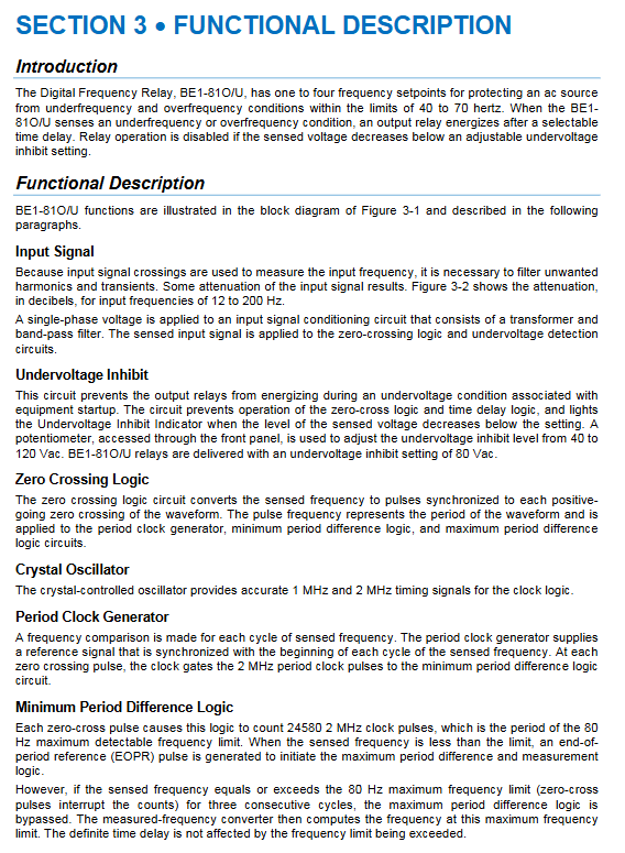
Chapter 3: Functional Principles of the Whole Machine
1. Complete signal processing link
External single-phase AC sampling → bandpass filtering shaping → zero crossing detection circuit, extracting waveform rising edge pulses; Compare the waveform period of the 1/2MHz reference clock of the crystal oscillator, convert the measured frequency, and send the BCD code to the comparator.
2 Core Logic Processes
Low voltage lockout discrimination: If the sampling voltage is lower than the set value on the panel, all frequency comparison and timing circuits will be directly blocked, and the low voltage alarm light will light up;
Frequency comparison: Compare the measured frequency with the set values of each group of dialing codes, with O-mode overclocking start and U-mode low-frequency start;
Three cycle anti shake: Only when the frequency is abnormal for three consecutive cycles, will the Pickup indicator light be triggered to filter out instantaneous frequency fluctuations;
Fixed delay timing: Accumulate timing based on S7 magnification/unit setting, and drive the main trip, auxiliary contact, and latch fault light after delay;
Fault reset: The frequency returns to normal and lasts for 3 cycles, the Pickup light goes out, and the output contacts reset; The fault light needs to be manually reset and cleared.
3 Key Hardware Module Description
Crystal oscillator benchmark: high-precision clock ensures 0.01Hz frequency resolution accuracy;
Cycle Extreme Value Logic: Distinguish between the lower limit of 30Hz and the upper limit of 80Hz, and calculate the delay based on the boundary value when exceeding the limit;
Power module: Wide range isolated flyback power supply, non-polar AC input, optional power failure alarm normally closed contact;
There are two types of fault indicator lights: built-in driver (no need for large tripping current) and current driver (can only light up when the circuit is ≥ 200mA).
Chapter 4 Installation, Wiring and Maintenance
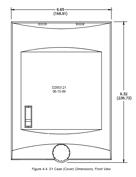
1. Mechanical installation
There is no limit to the installation angle, and there is no tilt requirement for solid-state circuits;
Complete set of opening, side view, and back panel dimension drawings (S1/M1 shell separated);
Grounding mandatory requirement: The grounding terminal of the independent 12AWG copper wire grounding device is prohibited from sharing the power ground bar.
2 Terminal and wiring specifications
The terminal can be plugged and unplugged to disconnect the trip circuit and improve maintenance safety;
Conventional signal line ≥ 14AWG, grounded 12AWG;
Typical wiring: single-phase PT voltage sampling, DC trip circuit, auxiliary alarm circuit;
The plug-in bracket is easy to replace on site and does not require rewiring.
3 Maintenance and Storage
No regular disassembly and maintenance, only annual full functional testing;
Idle spare parts are powered on for 30 minutes every year to activate electrolytic capacitors and extend their lifespan;
Hardware failures are prohibited from being dismantled or returned to the factory for repair without authorization.
Chapter 5 Standardized Whole Machine Testing Process
1. Essential testing equipment
Adjustable frequency conversion AC source, AC/DC power supply, timing instrument, multimeter; The frequency stability requirement for the variable frequency source is within 0.00002Hz.
Step by step standard testing procedures
Frequency startup value verification: Test the over frequency and under frequency gears separately, and the measured value error is ≤± 0.01Hz;
Cycle delay test: Set the magnification and cycle, measure the action time and verify the theoretical calculation value;
Second level delay test: Fixed second level, verifying that the delay is not affected by frequency changes;
Low voltage lockout test: Slowly reduce the sampling voltage, and after it falls below the set value, the frequency protection will be completely locked;
Repeat the above complete set of tests with multiple sets of fixed values (2/3/4 channels) to verify that the channels are independent and do not interfere with each other.