Basler BE1-700V digital voltage protection relay
Hardware, installation, and terminal wiring
1 Shell and installation
Structure: Fixed panel installation, non removable, no plug-in modules; Provide complete panel openings, dimensions in inches/millimeters for length, width, and thickness; It can be installed at any angle without any mandatory vertical requirements.
Maintenance suggestion: The backup equipment should be powered on for 30 minutes every year to extend the electrolytic capacitor; The whole machine is only tightened for preventive maintenance of wiring. If there is a fault, it should be returned to the factory for repair. It is prohibited to disassemble the machine by oneself.
2 Input/Output Hardware Resources
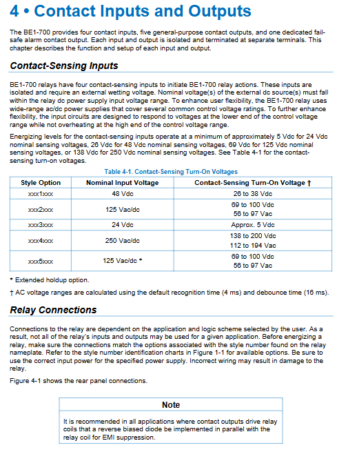
4-channel programmable switch input IN1~IN4
Driven by an external DC wet power supply, it can set recognition time (4~255ms) and anti shake time (4~255ms) for circuit breaker position, external locking, and remote signal acquisition.
Output circuit
5-way universal normally open contacts OUT1~OUT5: capable of assigning trip, alarm, and remote control outputs, supporting 200-2000ms to maintain anti shake; OUT1 built-in trip circuit monitoring 52TCM;
1-channel fault safety normally closed alarm output OUTA: device crashes/loses power and automatically closes, used for overall device fault alarm;
The output drive coil must be connected in parallel with a freewheeling diode to suppress EMI interference.
Voltage acquisition terminal
VA/VB/VC three-phase PT, VN neutral point, Vx auxiliary voltage (can be connected to open delta 3V0, single-phase PT), supports 3-wire/4-wire, star/delta PT secondary wiring.
communication terminal
Front panel USB-C local debugging; Backplane RS485, RJ45 Ethernet (optional), IRIG-B timing; The independent grounding terminal requires a 12AWG copper wire single point grounding.
3 Typical Wiring
Including three-phase four wire PT, three-phase three wire PT, single-phase PT, synchronous parallel dual PT, trip circuit, circuit breaker position, remote control, RS485/Ethernet complete set of standard wiring diagrams; Distinguish between primary circuit voltage acquisition and secondary control circuit wiring, and recommend cables of 14AWG or higher.
Front panel human-machine interface HMI
Hardware components: 64 × 128 backlit LCD, power green light, device fault red light, size alarm light, trip latch red light USB-C、 Reset button, edit button, four-way navigation button.
The screen menu has two main branches:
Measurement branch: real-time voltage/phase sequence/frequency/synchronization difference, equipment status, fault events;
Set branches: system parameters, all protection settings, communication, logic, permissions, time;
Operation function:
The editing mode requires a graded password and will automatically exit after 5 minutes of inactivity;
Reset button to clear latch trips and alarms;
Screen sleep mode with adjustable backlight delay, supporting automatic screen rotation for real-time data.
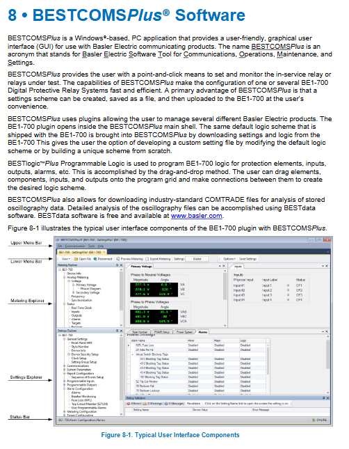
Supporting upper software BESTCOMSPlus
1 Operating environment
Windows7 SP1/8.1/10/11, Minimum 1GB of memory, pre installed with. NET framework, installed with administrator privileges, built-in BE1-700 dedicated plugin, matched with offline logic simulator and waveform analysis tool BESTdata (reading COMTRADE standard waveform files).
2 core functions
Communication methods: USB direct connection, Ethernet RS485; Support device search and automatic reconnection;
File management: Save/upload/download fixed values and logic files (. bst4 fixed values,. bsl4 logic library), support file comparison, batch export CSV measurement data;
Visual configuration:
Set browser: subsystem, protection IO、 Communication and alarm tree menu;
Measurement Browser: Real time phase voltage, sequence voltage, frequency, synchronous phase angle, phasor diagram, supports window floating split screen;
BEST logicPlus graphical programmable logic: drag and drop components, connect wires to build protection logic, offline simulation verification;
Firmware upgrade: The software uploads the firmware of the entire machine, and after the upgrade, it is restored to the factory. It is necessary to re import the settings;
Multilingual: including Simplified Chinese interface.
Permission and Security Management
Adopting a 6-level hierarchical access permission, different communication ports (USB/Ethernet/485) can independently set password free/password access levels:
Level 6 Admin: Add or delete users, modify all security configurations;
Level 5 Design: Editing Programmable Logic;
Level 4 Settings: Modify all protection settings;
Level 3 Operator: Zeroing metering, event recording;
Level 2 Control: Remote control switch and circuit breaker operation;
Level 1 Read: View only, no modification permission;
Valid period of matching password, lock upon login failure, automatic downgrade to read-only upon access timeout; You can set whether a password is required for resetting the front panel separately.
System basic configuration (power supply, PT, clock, settings group)
1. Power system parameters
Set PT secondary phase voltage, rated frequency 25-60Hz, phase sequence ABC/ACB; Distinguish between three-phase 3W/4W, single-phase, and Vx auxiliary PT wiring modes, automatically calculate positive sequence V1, negative sequence V2, zero sequence 3V0, and third harmonic voltage. Sample 32 points per cycle and automatically adjust the sampling rate with frequency.
2 Clock System
Built in real-time clock, supporting local time zone and daylight saving time; IRIG-B code synchronous timing; All faults and SOE events are marked with high-precision timestamps, and clock loss triggers alarms.
3 Double Fixed Value Groups (Group0/Group1)
Two independent sets of complete protection settings, which can be automatically switched through switch input, reclosing status, PT disconnection 60FL; Lock the fault record during switching to avoid misjudgment of actions; Support logical output to indicate the current activated fixed value group, and can set the switching anti shake delay.
Complete set of protection and control functional components (core protection logic)
All functions of the device are independent logic blocks that can be freely configured through BEST logic. They all support delay, lockout, action alarm, and fault recording triggering
1. Voltage protection
24 overexcitation protection (V/Hz)
Monitor the Hertz ratio to prevent transformer core saturation and overheating; Support inverse time limit (3 types of exponential curves), two-stage fixed time limit, with pre alarm threshold, can set cooling reset curve, and adapt to main transformer and plant transformer protection.
25 synchronous inspection
Parallel closing interlock, while verifying voltage difference, sliding frequency, and phase angle difference; Distinguish between active/passive bus detection, compensate for different PT phase angle offsets, and can be locked by PT disconnection 60FL.
27P phase undervoltage (2 independent groups)
Three phase phase voltage low voltage protection, with optional 1/2/3 phase operation modes, and a low voltage lockout threshold set for low voltage load shedding and voltage loss tripping.
27X auxiliary undervoltage
Monitor 3V0 zero sequence, Vx fundamental wave, and Vx third harmonic for monitoring grounding imbalance and generator neutral point voltage.
47 negative sequence overvoltage
Detect phase loss, phase sequence reversal, severe three-phase imbalance, and motor/bus imbalance protection.
59P phase overvoltage (2 groups)
Phase voltage overvoltage protection, suppressing load shedding overvoltage and resonance overvoltage.
59X auxiliary overvoltage
Zero sequence overvoltage and open delta grounding fault monitoring.
2 frequency protection (81, a total of 6 independent components)
Can be configured separately for overclocking/underflocking, monitoring three-phase main voltage or auxiliary Vx, with low voltage lockout, islanding protection, and dedicated for high-frequency switching of distributed power sources.
3 PT disconnection protection 60FL
Identify PT fuse breakage and secondary disconnection based on positive and negative sequence voltage criteria; It can automatically lock all voltage protections of 25/27/47/59 to prevent PT from tripping due to voltage loss and triggering special alarms.
4 Control Logic Components
43 virtual control switches (4 channels)
No external physical contacts are required, and the panel/software can be set/pulsed remotely for on/off protection and switching operation modes; Support listing and locking.
62 Universal Logic Timer (2 channels)
6 working modes: start return, monostable state, resettable, oscillation, integration, self holding, used for logic delay, closing delay, interlocking timing.
79 automatic reclosing
Up to 4 reclosing sequences can be set, with two modes: lockout reclosing, remote start, downstream fault counting coordination, and lockout/restore after power loss. It is matched with closing failure and maximum operation timing.
101 Circuit Breaker Virtual Control
Remote/local switch on/off pulse output, memory switch on/off position auxiliary contact, with operation tag function.
52TCM trip circuit monitoring
Continuously monitor the continuity of the OUT1 trip coil circuit, and immediately issue a device alarm if there is a disconnection or voltage loss.
8 BESTlogic ™ Plus Programmable Logic System
Device core configuration tool, graphical drag and drop programming, replacing traditional secondary wiring:
Component library: protection block, timer, virtual switch, gate circuit (AND/OR/XOR/latch, rising and falling edge trigger, counter), input and output terminals;
Paging drawing, supports signal transmission between pages, comes with offline simulation, can simulate all logical state verification interlocks;
Logic can be saved and reused separately, and logic errors (floating ports, illegal connections marked in red) will be automatically verified before downloading;
All protected Pickup starts, Trip trips, and Block locks can be freely bound to input, output, alarm, and recording triggers.
Communication, Recording, and Alarm System
Multiple communication interfaces
Local USB-C: only for debugging, uploading, and downloading;
RS485:Modbus RTU, Customizable address, baud rate, and verification;
Ethernet RJ45: Simultaneously running BESTCOMSPlus+Modbus TCP, DHCP automatic/static IP;
Supporting independent Modbus manual 9376700997.
2 Fault recording function
Fault total report: stores 16 event loop coverage, recording time, fault type, activation set value group, reclosing status, and target of each protection action;
COMTRADE standard waveform recording: 32 samples per cycle, up to 16 sets of waveform recording, recording voltage, frequency, and sequence components before and after faults, and can export BESTdata analysis;
SOE event sequence recording: switch displacement, protection activation, device alarm with millisecond time scale.
3 Alarm System
There are three types of latch alarms: Major, Minor, and internal device faults, which will not be lost during power outages; Customizable whether each protection can trigger an alarm and reset; Circuit breaker operation exceeding limit, clock loss, communication interruption, and firmware abnormality are all equipped with built-in alarm logic.
Complete set of test specifications
The manual independently divides acceptance testing, commissioning testing, regular calibration, and separate testing chapters for each protection, providing standard testing steps, voltage/frequency application methods, and error judgment standards for each type of protection
24 V/Hz overexcitation curve verification;
25 synchronous angle/pressure difference/frequency difference test;
27/59 High and low voltage setting and delay test;
47 negative sequence imbalance simulation;
81 frequency protection up and down frequency test;
60FL PT disconnection simulation;
79 reclosing timing test;
52TCM trip circuit monitoring and verification;
IO input/output on/off, logic simulation testing.
Electrical and Environmental Specifications
Power supply: 24/48/125/250V AC/DC wide range, low-power isolated power supply;
Contact capacity: 120VAC continuous 7A, DC breaking 0.3A inductive load;
Voltage resistance: 2121VDC to ground, 1500VAC between circuits; Surge resistance and radio frequency interference comply with IEEE C37.90;
Environment: Wide temperature operation, three-axis 15G impact, 2G vibration, UL508 certification.