Basler BE1-851 Overcurrent Protection Device Manual
Product positioning
BE1-851 is a Basler microcomputer based multifunctional overcurrent protection relay, which is mainly used for non directional overcurrent protection scenarios such as distribution network feeders and plant power. It integrates protection, circuit breaker control, fault recording, event recording, metering, programmable logic, and remote communication. It supports the transformation of old and old electromagnetic relay cabinets and offers multiple chassis sizes (S1 standard rack, H1 half rack, F1 Westinghouse FT11 specification).
Hardware and electrical specifications of the entire machine
1. Hardware sampling distinguishes between two major models
H-type sampling: 2-phase instantaneous, 2-phase neutral instantaneous, 2-phase negative sequence instantaneous; 1 phase/1 neutral/1 inverse time overcurrent, suitable for phase imbalance and motor negative sequence faults;
G-type sampling: 2-phase, 4-channel neutral instantaneous; 1-phase, 2-channel inverse time neutral, focusing on ground fault protection, without native negative sequence components.
2. Simulate current input
Standard 5A/1A CT secondary input, 24 point/cycle 16 bit AD sampling; Supports three current algorithms that can independently configure phase/zero sequence:
Fundamental fundamental wave: filtering out harmonics, preferred for protection, with minimal transient exceedance;
Wideband RMS full wave effective value: including all harmonics, used for thermal overload monitoring;
Average: Wide frequency adaptation for old disc relays.
Rated operating condition continuous current of 20A (5A model), short-term 400A/1s, CT burden is extremely low (≤ 0.004 Ω).
3. Switching IO
4-channel programmable passive input IN1~IN4: can set 4~255ms recognition/stabilization time, compatible with AC/DC control power supply;
5-way universal output OUT1~OUT (A-type normally open tripping contact), 1-way fault safety alarm output OUTA (normally closed/normally open optional);
The output meets the IEEE tripping load standard, with a single contact short-term 30A and long-term 7A.
4. Power supply specifications
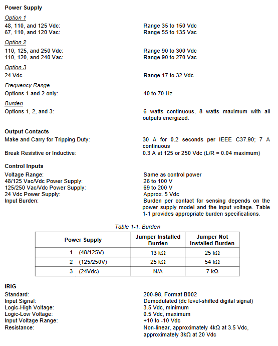
Three levels of optional power supply: 24Vdc, 48/125Vac/dc, 125/250Vac/dc, with a total power consumption of 6W and a full load of 8W.
5. Clock and Timing
Built in real-time clock, with a capacitor backup that can maintain 8 to 24 hours of travel time; Optional lithium battery (with a range of 5 years); Supports IRIG-B demodulation code timing, with the ability to configure 12/24-hour clock, time zone, and daylight saving time.
6. Communication hardware
Front panel COM0: RS232, local debugging;
Back panel COM1: RS232 remote serial port;
Backplane COM2: RS485, supports Modbus/DNP3/ASCII;
The baud rate ranges from 300 to 19200, and the three ports are independently isolated without preempting each other’s access.
7. Panel human-machine
Two lines of 16 character backlit LCD, 5 status LEDs (power, device failure, secondary alarm, primary alarm, trip), Edit key+Reset key; When there is a malfunction, an automatic pop-up window will display the target of the malfunction.
Detailed explanation of the core functional modules of the whole machine
(1) Four fixed value groups (SG0~SG3) adaptive protection
The device supports 4 sets of independent protection settings to achieve load adaptive switching:
Manual switching: Select groups manually through virtual input/ASCII commands/HMI;
Automatic switching: Monitor the 51 overcurrent load threshold, automatically switch to high setting for heavy load and sensitive setting for light load, and support cold load recognition;
Switching lockout: Switching is prohibited during fault pickup to prevent protection failure;
The group switching alarm and timing anti jitter delay can be configured.
(2) Complete set of overcurrent protection components (ANSI standard)
50 instantaneous overcurrent (with adjustable delay)
Phase 50TP/150TP, neutral 50TN/150TN/250TN/350TN, negative sequence 50TQ; adjustable delay from 0 to 60 seconds, with logic locking input, fault picking and tripping dual logic output.
51 inverse time overcurrent
51P phase, 51N neutral, 51Q negative sequence; Built in IEEE standard multiple characteristic curves (GE IAC, Westinghouse ABB, IEC, user-defined curves), supports integral reset characteristics, can set time dial and pick up current.
Negative sequence protection (exclusive to H model)
For two-phase short circuits, motor phase breaks, and phase to phase faults, the equivalent conversion setting is 1.732 times, suitable for low-voltage grounding backup protection of delta/star transformers.
(3) Circuit breaker failure protection BF
Detecting continuous fault current after fault tripping, triggering failure and remote tripping when timeout occurs; 50ms minimum delay, equipped with a fast current detection circuit, can be logically locked and externally triggered.
(4) 79 automatic reclosing
Up to 4 overlapping sequences, supporting multiple power on modes (power on lock/power on close); Configurable intervals, reset timing, and maximum cycle time limit; Support segmented locking (SCB), downstream fault identification, and automatic switching of protection setting groups during the coincidence process.
(5) Universal Logic Timer 62/162 (added 262 and 362 for V/W models)
6 working modes: pick and disconnect, single trigger non resettable, resettable, oscillator, integrator timer, self-locking; Used for delayed alarm, interlocking, and locking logic.
(6) Virtual control components (without physical wiring)
43 series virtual selection switch: local/remote HMI/serial port operation, simulating local switching of pressure plates;
101 Virtual Circuit Breaker Control Switch: Virtual on-off pulse output, 200ms short-term output, no need for external control switch.
Measurement, recording and alarm system
1. Real time measurement
Real time measurement of three-phase, neutral, and negative sequence currents with an accuracy of ± 1%; Real time interface/software refresh, supporting switching between primary/secondary current units.
2. Demand statistics (exponential algorithm)
Separate demand windows for phase separation, zero sequence, and negative sequence, recording today’s peak value, yesterday’s peak value, and peak value after reset, with automatic alarm for exceeding the threshold.
3. Circuit breaker monitoring
Switching operation counter;
Fault breaking I/I ² cumulative capacity, reaching threshold alarm;
Continuous monitoring of trip circuit (TCM, hardware bound OUT1 circuit, detecting fuse failure and coil breakage);
Measure the opening time and record the duration of fault clearing.
4. Fault recording system
Fault targets: Record triggering protection components, panel TRIP light latch;
Fault Summary Report: Stores 16 pieces of fault information, including time, group, fault current, and coincidence status;
COMTRADE standard waveform recording: 15 cycles per recording (3 weeks of pre fault+12 weeks of fault segment), up to 16 sets of waveform files, supporting BESTWAVE software analysis;
SER event sequence recording: 255 events, 1ms time scale, recording all IO, logic, alarm displacement, used for fault timing replay.
5. Grading alarms
Fatal alarm of the device (RAM/ROM/power/AD failure): directly lock all outputs, OUTA action;
Main alarm Major, secondary alarm Minor: customizable 26 types of system/device alarms (communication loss, clock failure, coincidence failure, overload, etc.);
User logic alarm ALMLGC: Custom logic triggers alarm output.
BEST Logic Programmable Logic (Core Features)
Design logic: Digital version secondary wiring, with each protection/IO/timer as an independent functional block, interconnected through Boolean expressions (AND/OR/NOT), replacing traditional hard wiring;
Two logical modes: pre fabricated standard feeder logic (one click activation) and user-defined logic (freely built);
Distinguish between two types of settings:
Function block logic: enable/lock components, bind logic inputs;
Virtual output logic: mapping hardware trip and alarm contacts;
Support virtual intermediate variables VO1~VO15 to achieve complex interlocking, pressure plate simulation, and alarm linkage;
The supporting software BESTCOMS can be used for visual drag and drop programming, and logic can also be edited through ASCII serial port commands.
Three layer human-machine operation mode
1. Panel local HMI
Six sets of menus: status, control, metering, fault recording, protection settings, system settings; Support password grading, automatic fault pop-up, Reset button to reset targets and alarms.
2. ASCII serial port command
Fully functional text instruction set, divided into five categories of instructions: C control, G global safety, M measurement, R report, S constant value; Supports single read/write and batch text file loading and unloading of fixed values, suitable for automation backend and debugging terminals.
3. BESTCOMS upper software (Windows platform)
Offline editing of settings and logic, and on-site installation of devices;
Built in all prefabricated protection logic and curve library;
Wave recording file download and analysis, constant value comparison function;
Firmware upgrade, batch device unified configuration;
Support exporting fault data and printing reports.
Permission security management
Four level independent passwords: fixed value, report, device control, global administrator;
Port access isolation: The front panel and front and rear serial ports can separately block write operations and only allow read-only access;
Automatically log out after 5 minutes of inactivity, with no saved modifications and loss alarm;
All write operations and login behaviors are recorded in the security audit log;
The administrator password is lost and there is no on-site reset plan. It must be returned to the factory for repair.
Installation, wiring, testing and maintenance
Installation: Multiple specifications of openings, compatible with GE, ABB, and Westinghouse old-fashioned relay cabinet adapter brackets, can be installed at any angle;
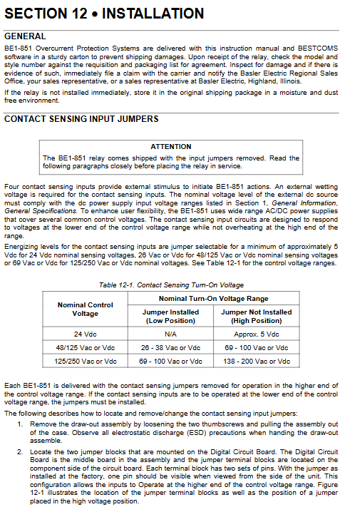
Wiring specifications: CT circuits are prohibited from open circuits, and there are clear standards for terminal tightening torque to distinguish AC/DC input jumpers;
Factory operation and regular complete testing process: protection components, reclosing, communication, waveform recording, alarm full item verification;
Troubleshooting chapter: Typical fault location solutions such as communication failure, protection misoperation/refusal, IO abnormality, clock loss, etc.