Basler BE1-11g comprehensive protection device for generator
Product positioning
BE1-11g is an integrated multifunctional generator microcomputer protection and measurement device, which integrates all generator standard ANSI protection, synchronization control, circuit breaker management, energy metering, fault recording, event SOE, programmable logic BEST logic Plus, and multi protocol communication. It replaces multiple independent electromagnetic/digital relays and supports single machine, plant, grid connected, off grid, and high resistance grounded generator scenarios. It can also choose automatic synchronization, remote RTD temperature measurement, and IEC61850 digital station functions.
Hardware and Human Computer Interface
1. Differentiation of chassis models (J/H/P three types of cabinets)
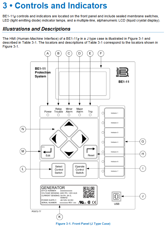
J-type: 12 LED indicator lights, 10 input channels, up to 8 output channels, with dedicated virtual switch operation buttons;
H/P type: Simplify 5 status LEDs, 4 input channels, 5 universal output channels;
Unified configuration of 128 × 64 backlit LCD, front USB debugging port, rear RS485, optional Ethernet.
2. Panel operation function
Four way navigation key+Edit+Reset, graded password permissions (Level 6 permissions: read-only/control/operator/fixed value/design/administrator);
LCD automatically prioritizes displaying alarms and fault targets, supports screen sleep, language switching (English/Russian), and contrast adjustment;
Fault/trip LED with memory latch, manual reset required; The panel can directly view real-time quantities, fixed values, events, and switch status.
3. Switching I/O system
Input circuit
Can be jumper adapted to 24/48/125V AC/DC control voltage;
Each input has anti shake and independent adjustable recognition time, and the logical variables can be customized with names and divided into two status labels: live/dead;
It can collect circuit breaker position, external protection locking, constant value switching, synchronous permission, and remote control signals.
Output relay
Universal outputs are all trip level contacts, with one dedicated fault safety alarm output OUTA;
Each output supports holding timer, forced setting/pulse testing (debugging specific);
When the device self checks a serious fault, all outputs are forcibly locked, and only the alarm contact is activated.
4. Sampling input hardware
CT: Supports 1A/5A secondary, optional dual group CT (main transformer+generator), low load design;
PT supports three-phase three wire, three-phase four wire, single-phase, and auxiliary Vx residual voltage input (3rd harmonic grounding detection);
Optional external RTD temperature module (up to 14 winding/bearing temperature measurements);
The sampling adopts DFT discrete Fourier algorithm to filter harmonics and accurately calculate sequence components (positive sequence V1, negative sequence V2, zero sequence 3V0, I2 negative sequence current).
5. Three independent isolation interfaces for communication hardware
Front USB: local BESTCOMSPlus debugging, priority channel;
Rear RS485: Modbus RTU, DNP3;
Optional Ethernet RJ45: Modbus TCP, DNP3, IEC61850, NTP network timing;
Clock synchronization: Supports IRIG-B hard clock synchronization and NTP network, with a backup capacitor to maintain 24-hour operation and a lithium battery for long-term backup.
Complete set of ANSI standard generator protection components
The manual provides for each type of protection: action principle, criterion formula, logic diagram, setting interface, locking conditions, trip/alarm output, curve configuration, and test methods.
1. Voltage protection (24/25/27P/27X/59P/59X/47/78V)
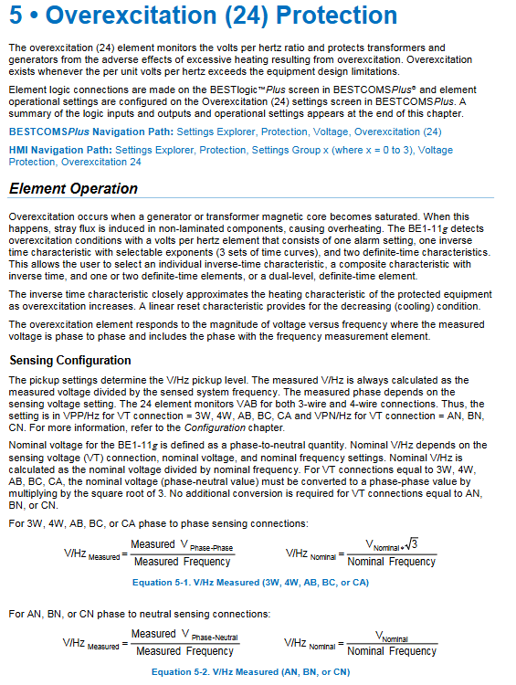
24 overexcitation (V/Hz): prevents magnetic flux saturation of the generator/main transformer, supports inverse time limit+two-stage timed composite curve, can alarm separately, delay tripping, PT disconnection 60FL can be locked;
25. Simultaneous inspection: necessary for grid connection, while verifying voltage difference, frequency difference, and phase angle difference; Distinguish between voltage/non voltage switching logic, support angle compensation to adapt to Δ/Y transformers; Optional 25A automatic synchronization plugin, automatically adjusts voltage and frequency for grid connection;
27P phase undervoltage/59P phase overvoltage: 5 sets of undervoltage, 4 sets of overvoltage, can be configured with 1/2/3 phase action, supports timed/custom inverse time curve, used for load shedding and power loss protection;
27X auxiliary undervoltage/59X auxiliary overvoltage: Monitor the third harmonic of Vx residual voltage (100% stator grounded 64G core component), positive and negative sequence voltages, and achieve high resistance grounding fault protection for the generator;
47 negative sequence voltage: monitor three-phase imbalance and asynchronous closing;
78V out of step vector jump: islanding protection, detecting sudden changes in voltage phase angle when the power grid is lost, quickly tripping the grid switch to prevent asynchronous coincidence.
2. Frequency protection (81 out of 8 components)
Support overclocking, low-frequency, df/dt frequency change rate (islanded high-frequency core protection); Main PT or Vx residual voltage can be selected as the sampling source, and low voltage lockout can be configured to prevent PT disconnection and misoperation; The IEC61850 model is reduced to 4 low frequencies+2 overclocking+2ROCK.
3. Current protection (50 instantaneous/51 inverse time/46 negative sequence/67 direction)
50 instantaneous overcurrent 6 groups: three-phase, grounded, negative sequence, unbalanced multiple modes, with directional locking;
51 inverse time overcurrent 7 groups, built-in 22 international standard curves (IEEE/GE/ABB), supporting user-defined curves and voltage constraints (specifically for generator backup protection); 46 negative sequence currents are integrated into 51 components, matching the generator’s I ² t heating limit;
67 direction overcurrent: positive sequence, negative sequence, zero sequence multi polarization mode (voltage/current polarization), distinguishing forward/reverse faults, used for selective tripping of phase to phase grounding faults in grid connected lines.
4. Differential main protection (87 differential/87N neutral differential)
Only supports differential hardware models, generator main protection:
87 phase current differential: dual slope percentage braking, 2/5th harmonic surge blocking, transient CT saturation monitoring, divided into two CT wiring modes: ordinary proportional braking and flux balance;
87N neutral point differential: sensitive stator grounding protection, monitoring the difference between neutral point 3I0 and machine end grounding CT, suitable for Y-shaped high resistance grounding units.
5. Power and demagnetization protection (32 power/40Q reactive type/40Z impedance type)
32 sets of forward/reverse power: to prevent reverse power of the generator (turbine losing steam and reversing the motor), and to connect to the grid for reverse power transmission; Can be divided into three-phase total power or phase separation action;
40Q reactive power demagnetization: monitoring the absorption of a large amount of reverse reactive power by the generator, with simple demagnetization protection;
40Z impedance circle demagnetization: Double offset Moho circle, accurately distinguishing low load/full load demagnetization conditions, standard configuration for large generators.
6. Distance from backup 21, out of step 78OOS, circuit breaker failure 50BF
21 distance protection for two segments of Moho impedance characteristics, used as a generator step-up transformer and remote backup for outgoing lines; Support Δ/Y variable angle compensation;
78OOS Out of Step Protection: Monitor the rate of impedance change, distinguish between oscillation and short circuit, and prevent damage to the shaft system caused by unit out of step;
50BF circuit breaker failure: After protection tripping, the fault current continues, and the upstream power supply is delayed to trip. Dual criteria (current presence+circuit breaker position).
7. Temperature protection 49RTD
External RTD module collects stator/bearing temperature, with multi-stage constant value alarm and tripping.
8. Stator grounding 64G (27X+59X combination)
Utilizing the third harmonic voltage of the PT terminal and the zero sequence voltage of the neutral point to cover 0-100% of the entire stator winding grounding fault, it is essential for high resistance grounded generators.
9. PT disconnection 60FL, trip circuit monitoring 52TCM
60FL detects PT fuse melting and automatically locks all voltage dependent protections (24/25/27/59/21/40Z, etc.);
52TCM continuously monitors the disconnection and voltage loss of the trip coil circuit, and provides early alarms.
Control, Logic, and Fixed Value System
43 virtual control switches with 5 groups: both local panel and remote communication can switch on/off, switch on/off protection, and switch operating conditions; Support pulse/hold mode;
8 sets of 62 programmable logic timers, 6 timing modes, to build complex interlocks;
86 locking element: After a fault trip, manually reset the overall locking to prevent multiple fault impacts;
101 circuit breaker virtual control: remote/local opening and closing, with anti misoperation logic;
4 independent constant value groups: normal/cooling load/emergency/special working conditions, can be switched automatically by logic or external contacts, adapted to different operating modes of unit start stop, grid connection, and islanding;
BEST logicPlus visual programmable logic: drag and drop graphical programming, all protection inputs and outputs, on/off switches, timers, virtual switches are freely interconnected, custom interlocking, alarm, and trip logic are available, and offline simulation is supported.
Measurement, waveform recording, event and operation data
Real time measurement: three-phase voltage/current, sequence components, active/reactive/power factor, frequency, RTD temperature;
Electricity statistics for positive/negative active and reactive hours;
Demand statistics show the maximum load of custom windows for 1 to 60 minutes;
Long term continuous load storage of load curve;
IEC 61000-4-30 B-level standard for power quality, monitoring voltage dips, surges, and imbalances;
SOE event sequence recording: half cycle time scale, recording all inputs, protection actions, alarms, and constant value switching;
COMTRADE standard fault recording: pre – and post fault waveforms, accompanied by free BESTdata software analysis;
Life statistics of circuit breakers: cumulative number of operations, fault breaking I ² t, reaching threshold alarm.
BESTCOMSPlus upper software
Windows platform, supporting Win7~Win11, required NET framework;
Three connection methods: front USB, rear RS485, Ethernet;
Core functions: Whole machine graphical setting configuration, BEST logic logic drawing, parameter upload and download, batch copying of parameter files, waveform recording and export, curve drawing, protection single point simulation testing, batch printing of setting values;
The BESTdata free tool is used to read COMTRADE fault waveforms.
Communication, security, clock
Three channel independent communication does not interfere with each other and supports simultaneous access by multiple master stations;
Permission level password, which can restrict the read and write permissions of each communication port (such as Ethernet only allowing reading and prohibiting remote control);
Clock source priority: IRIG-B>NTP>local RTC, supports automatic correction during daylight saving time;
Optional IEC61850 GOOSE fast tripping and MMS data upload to meet the requirements of digital substations.
Installation, wiring, and terminals
Panel embedded installation, providing J/H/P type hole size;
Strong and weak electrical terminal zoning, CT/PT secondary strict grounding specifications;
Provide a complete set of standard wiring diagrams for three-phase three wire, four wire, residual voltage Vx, dual CT, and RTD modules;
Adjust the input voltage level of the terminal jumper and distinguish between high and low voltage control circuits.
Complete testing process
The manual provides standardized testing specifications, divided into three categories:
Factory acceptance test: complete machine power on, display, communication I/O、 Full clock inspection;
On site commissioning test: Each type of protective component is individually calibrated for action value, time limit, and locking logic;
Regular preventive testing: annual checklist of verification items;
The accompanying FAQ troubleshooting section covers common issues such as communication failure, protection misoperation, abnormal waveform recording, and no display on the panel.
Maintenance, spare parts, and hardware specifications
Tighten only the terminals on a daily basis and regularly backup the settings;
The only replaceable spare part: clock lithium battery (5-year replacement cycle);
Idle equipment can be powered on for 30 minutes every year to extend the lifespan of capacitors;
Complete hardware parameters: AC/DC working power supply, contact capacity, temperature and humidity, anti vibration and shock, various protection setting ranges, complete set of action time curve charts;
The independent chapter of RTD remote temperature measurement module includes wiring, parameter configuration, and temperature protection settings.