Basler DECS-400 Digital Excitation Control System
General Information and Machine Specifications
1. Core Five Control Modes
AVR automatic voltage regulation: constant terminal voltage regulation, voltage regulation accuracy ± 0.2%, dynamic response less than 1 cycle;
FCR excitation current regulation (manual): excitation current closed-loop, automatic switching to standby mode when voltage transformer breaks;
FVR excitation voltage regulation (manual): excitation voltage closed-loop, meeting the WECC unit test standards;
VAR reactive power constant control: grid connected constant reactive power output;
PF power factor constant control: grid connected constant power factor.
2. Summary of core functions
(1) Stable control
Two sets of PID parameters (PSS input/output two sets of parameters), built-in PID calculator, supporting two preset parameter libraries for main excitation machine/auxiliary excitation machine, and customizable PID.
(2) PSS power system stabilizer (optional 1XXX model)
IEEE PSS2A dual input architecture, accelerated power integration algorithm; Collect unit voltage, two-phase and above currents, and suppress low-frequency oscillations of 0.1-5Hz; Equipped with a complete set of functions including dual acquisition of speed/power, frequency locking, torsional filtering, multi-stage phase compensation, and output limiting.
(3) Limiting system (four major categories)
OEL overexcitation limit: divided into two types: summation type and takeover type, distinguishing between grid connected/off grid conditions, inverse time characteristic, with cooling timing;
UEL under excitation limit: Built in curve or 5-point custom unit phase advance curve to prevent step loss and stator end overheating;
SCL stator current limit: two time limits, short-term high constant value and long-term low constant value;
VARL reactive power limitation: adapted to scenarios of steam turbine expansion and constant generator capacity, limiting lagging reactive power;
V/Hz/low frequency limit: prevents excessive magnetic flux in the main transformer and generator, with adjustable slope and inflection point.
(4) Complete set of protection functions (12 items)
Excitation overcurrent, excitation overvoltage, excitation overtemperature, generator overvoltage/undervoltage, voltage loss detection, demagnetization (40Q), frequency below 10Hz, excitation diode open/short circuit, V/Hz overcurrent, isolation module fault, power supply low voltage; All protection belts have independent delay and dual set fixed values (main/standby units), which can drive relay alarm tripping.
(5) Grid connected parallel supporting function
Reactive power adjustment, cross current differential compensation, line voltage drop compensation, to achieve equal distribution of reactive power among multiple units.
(6) Preset position/disturbance free switching
Each control mode is set with 2 sets of preset fixed points, and the lifting speed can be adjusted; Automatic tracking between modes, dual DECS-400 redundant master-slave tracking, achieving interference free switching.
(7) Collection, measurement, and recording
Real time measurement: three-phase voltage, three-phase current, active/reactive/power factor, excitation voltage and current, temperature, frequency, frequency variation rate, etc; Two 4-20mA analog transmission outputs;
SER event sequence recording: stores 127 events, with a scanning accuracy of 50ms and time stamps;
Fault Oscillography: Compatible with COMTRADE standard, up to 6 channels, supports pre triggering, and can be viewed through BESTWAVE;
Long term trend record: up to 30 days of continuous parameter storage.
(8) IO interface resources
16 switch inputs: 6 fixed (AVR/manual/up/down/start/stop), 10 programmable;
8 relay outputs: watchdog, running status 2 fixed, 6 programmable (self hold/pulse/latch optional);
Analog control output: 4~20mA/0~10V/± 10V, choose one from three, drive external power bridge;
Auxiliary analog input: ± 10V or 4-20mA, remote setting, limited scaling, external PSS signal;
Dedicated excitation isolation module: collects excitation voltage and shunt current, isolates and sends them to the main control.
(9) Four communication interfaces
Com0: Front panel RS232, locally connected to BESTCOMS;
Com1: Backplane RS485, dual machine redundant master-slave tracking dedicated;
Com2: Backplane RS485, Modbus RTU;
Com3: RJ45 Ethernet 10BASE-T, Modbus TCP, NTP timing; Built in dial-up modem (read-only remote access); Supports IRIG-B clock synchronization.
3. Hardware and electrical specifications
Power supply: AC 120V or DC 24/48/125V two models;
Voltage/current transformer acquisition: PT secondary 120/240V, CT secondary 1A/5A, load < 1VA;
Excitation acquisition: The isolation module supports excitation voltages of 63/125/250/375/625V and 50/100mV splitters;
Environment: Operating at -40~60 ℃, weighing 680g, with CE, UL, GOST-R certification;
Real time clock: 3.6V lithium battery, 5-year replacement cycle.
Front panel HMI human-machine interface
1. Panel hardware
128 × 64 backlit LCD, 6 buttons (up, down, left, right navigation, edit, reset), 6 status LEDs (PSS activation, preset position, upper and lower limits, balance, edit); DB9 local RS232 port, pull-out modular structure, with locking buckle.
2. Menu 9 main branches
Operating status, constant value, PID loop gain, real-time measurement, protection, limiter PSS、 System parameters and general communication settings; Complete tree path, with a full menu path list attached in the manual.
3. Operations and Permissions
Editing process: Enter the corresponding interface → Press Edit → Enter password → Modify parameters → Save/Reset and discard; Automatically exit permission after idle for 10 minutes;
Two level password: global password (all parameters modified), fixed value password (only for simple operations such as lifting, mode, preset points, etc.); Factory default DECS4, when powered off, press Edit+Reset to restore default (will clear all custom parameters, need to be backed up in advance);
Measurement interface: Simultaneously display 3 real-time measurements, current fixed value percentage, operating mode, and alarm bar; Up to 6 cache alerts can be reset and cleared.
Detailed principle of function
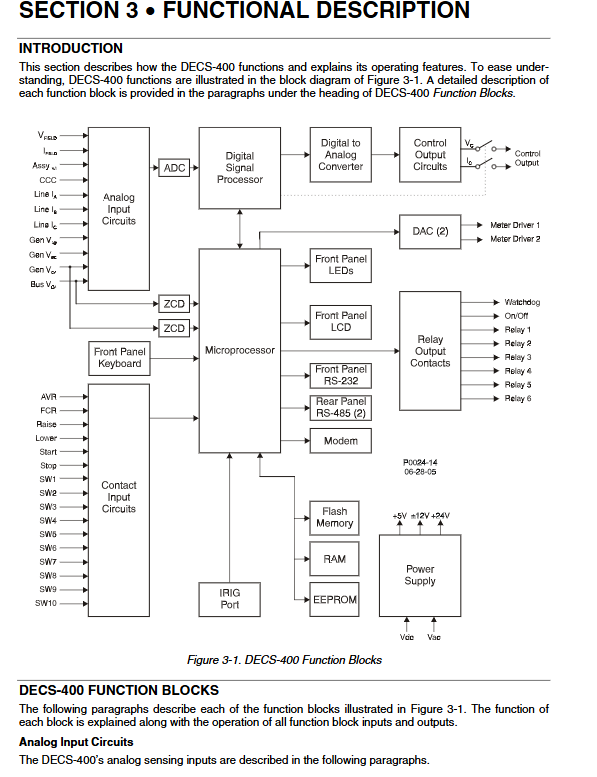
1. Hardware signal pathway
Analog acquisition (machine end/bus/stator current/excitation) → DSP digital filtering processing; Switch input detection; Four channel DAC outputs control signals and transmission signals; Relay logic output; Parallel processing with multiple communication processors.
2. Startup process
Soft start (voltage slowly climbing, anti surge top), excitation and voltage building logic; Pressure building failure alarm; Voltage matching function before grid connection, automatically tracks bus voltage.
3. Closed loop logic for each control mode
Describe the AVR/FCR/FVR/VAR/PID closed-loop regulation logic, lifting rate, upper and lower limits, and pre positioning maintenance/release modes separately.
4. Complete logic curve of limiter
Including SCL two-stage time limit, summation type OEL with three levels of grid connection/off grid, takeover type OEL inverse time limit curve, UEL five point phase advance curve, V/Hz ramp characteristics, accompanied by schematic diagram and timing formula.
5. Protect action logic
Explain the internal judgment logic of excitation overcurrent inverse time limit, V/Hz square inverse time limit, excitation diode monitoring EDM (using ripple to distinguish open circuit/short circuit), demagnetization protection leading phase criterion, unbalanced blocking PSS, etc. one by one.
6. Disassembly of PSS complete module
Speed channel, active power channel, mechanical power synthesis, torsional filtering, four stage phase compensation, washout filter, logic limiting, terminal voltage limiting, frequency blocking module, complete block diagram and transfer function parameter explanation are attached.
7. Redundant tracking mechanism
Internal tracking (undisturbed switching between different modes of the device), external tracking (one primary and one backup DECS-400 communicating via Com1, seamless switching of excitation in case of faults).
8. Wave recording/event triggering mechanism
Logic trigger, threshold trigger, manual trigger; Record variables that fully cover the unit, excitation PSS、 Limiter and control circuit signals.
BESTCOMS upper configuration software
1. Software Fundamentals
Windows platform, relying on NET framework, supporting equipment debugging, parameter backup, and experimental analysis tools, supporting DECS-300 parameter import.
2. Four communication connection methods
Front panel RS232, Ethernet TCP/IP, backplane Modbus 485, built-in modem (for viewing only, parameters cannot be modified); Ethernet supports DHCP/static IP and NTP network timing.
3. Classification of software core pages
System configuration: rated parameters of the unit, transformer ratio, excitation type, auxiliary input, transmission output, transient boost;
Fixed value settings: AVR/FCR/FVR/VAR/PF fixed value, preset position, soft start;
Gain page: Main/auxiliary two sets of PID (AVR/FCR/FVR/limiter/PF/VAR independent PI parameters), built-in PID calculator, input unit time constant to automatically generate gain;
Limiter configuration: OEL two modes, UEL curve SCL、VARL、 Limit value scaling;
Protection configuration: all protection settings, delay, and excitation diode monitoring parameters;
PSS complete configuration: complete set of parameters for switch selection, filtering, phase compensation, amplitude limiting, and frequency converter interlocking;
Logic programming: programmable and/or NOT gates, timers, custom interlocks, alarms, mode switching;
Real time monitoring: all electrical quantities, I/O status, alarms, and mode status;
Wave recording and trend: wave recording configuration, event viewing, COMTRADE export, long-term trend recording;
Analysis tools: step response test, frequency characteristic Bode plot, PSS signal injection test.
4. File function
Support saving/reading. de4 parameter files, printing parameters, text export, batch debugging and backup of devices.
Installation, commissioning, and maintenance
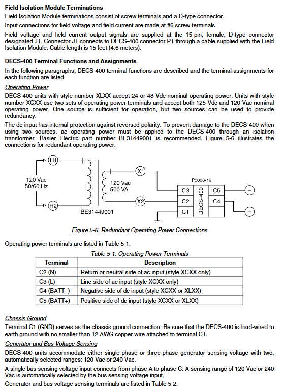
Installation: Installation dimensions of the entire machine, definition of backplane terminals, strong and weak electrical wiring (PT/CT/excitation/IO/communication grounding specifications), selection of isolation transformers, and requirements for wiring diameter;
Operation and commissioning: power on inspection, transformer polarity verification, excitation circuit inspection, no-load voltage regulation test, PSS setting, grid connected reactive power sharing, protection setting verification, redundancy switching test;
Maintenance: Daily inspection items, regular calibration cycle, lithium battery replacement (5 years), troubleshooting, hardware replacement steps.