Beckwith M-3520 distributed power grid connected comprehensive protection device
Overall positioning of the product
M-3520 is a microcomputer protection relay developed by Beckwith, a subsidiary of Hubbell, specifically for DER distributed power grid connection. It is designed for distributed power grid connection points such as photovoltaics, wind power, and energy storage, and integrates a complete set of grid standard protections for grid synchronization, abnormal power flow, phase to phase/ground faults, frequency and voltage disturbances, and loss of synchronization; Adopting DSP digital sampling, it integrates measurement, fault recording, SOE events, multi-channel communication, and programmable logic, providing 18 standard protections and 3 optional extended protections. It supports two configurations: basic simplified version and complete standard version, and is equipped with a complete set of options such as human-machine, optical, and upper software. It is universal for 50/60Hz, 1A/5A CT, 19 inch 3U standard rack, 5-year warranty for the whole machine, and has two US patents.
Supporting optional peripherals
M-3931 HMI local operation panel: 2-line 24 character LCD, three-level permission password, on-site setting and viewing of waveform recording events;
M-3915 Target fault light module: 24 protection action indicator lights, visually distinguish trip types;
M-3822 IPScom communication software: Windows platform remote read/write settings, SOE retrieval, and waveform recording;
M-3801D IPSplot waveform analysis tool;
Four wire RS-485 interface, dual redundant power supply.
Complete protection function (18 standard+3 optional, ANSI standard number)
(1) 18 standard protections (essential for grid connected core)
25 synchronous inspection (coincidence and grid connection logic)
Support criteria for hot grid connection and dead line/dead bus closure; Adjustable phase angle of 0~90 °, voltage difference of 1~50V, frequency difference of 0.001~0.5Hz; individually activated or combined with 79 reclosing, delayed by 1~8160 cycles; Capable of setting the closing threshold for voltage loss.
27 Three phase low voltage protection (two-stage constant value)
5~180V setting, divided into two algorithms: full waveform RMS/fundamental DFT, with independent two-stage delay.
27G/59G neutral point overvoltage/undervoltage protection
Monitor ground zero sequence voltage, adapt to ungrounded/resonant grounded distribution network, used for stator/line grounding warning tripping.
32 dual segment sensitive forward/reverse power protection
The standard value can be adjusted from -3 to+3PU, and reverse power can be set to prevent islanding and reverse transmission. The graded delay enables distributed power generation to be split in batches.
46 Negative sequence overcurrent (timed/inverse time limit)
Suitable for three-phase imbalance and single-phase disconnection faults, providing multiple IEC/universal inverse time curves and rotor/equipment overheating protection.
47 Negative sequence overvoltage protection
Asymmetric fault and disconnection generate negative sequence voltage alarm tripping.
50 phase instantaneous overcurrent
Short circuit quick break protection, quickly cutting off phase to phase faults.
50G instantaneous zero sequence overcurrent at neutral point
Ground fault quick break.
51V voltage control/voltage limit inverse time phase overcurrent
Automatically raise the action current threshold under low voltage faults to prevent low voltage false tripping.
51G zero sequence inverse time overcurrent
Long term grounding fault backup protection with multiple inverse time curves to choose from.
59 Three phase overvoltage (two-stage)
Grid connected overvoltage and islanding boost protection.
59I peak overvoltage (specifically for ferromagnetic resonance)
Capture instantaneous peak resonance voltage and specifically suppress PT and transformer resonance damage.
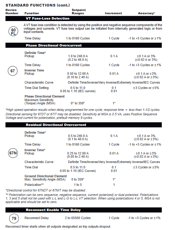
60FL PT disconnection detection locking
Based on the positive and negative sequence criteria, PT fuse automatically locks all voltage protection against misoperation and can output alarm contacts.
67 phase direction overcurrent (timed/inverse time limit)
The maximum sensitivity angle can be set, with forward fault tripping and reverse locking, to distinguish between internal and external short circuits.
67N zero sequence direction overcurrent
Supports multiple polarization modes of zero/negative sequence/current, accurately distinguishing the direction of grounding faults.
79 reclosing switch on/off logic
After the fault trips, the timer automatically recloses the contact switch when the synchronization conditions are met, with a delay of 2-65500 cycles.
81O/U four segment over frequency/low frequency protection
0.01Hz high-precision tuning, distributed power islanding, system frequency collapse and disconnection core protection.
6-way programmable external input expansion protection contacts, external protection such as grounding transformer and excitation are uniformly recorded for tripping.
(2) 3 optional extension protections (order as needed)
21 Dual segment phase offset Mjolz distance protection
Backup for inter phase faults in long lines, with two independent impedance circles, impedance angles, and delay settings.
78 out of step protection (oscillation locking)
Mjolz characteristics+shielding elements, monitoring power angle sliding poles, distinguishing short circuits from system oscillations, preventing false tripping of contact switches.
81R frequency change rate ROCOF
Island detection core protection, frequency sliding 0.1~20Hz/s setting, quickly identify isolated network conditions and disconnect power supply.
Measurement, recording, and event storage capabilities
1. High precision measurement of full power consumption
Collect three-phase/zero sequence/positive and negative sequence voltages, three-phase/zero sequence currents, active/reactive/apparent power, power factor, impedance, and frequency;
Voltage accuracy ± 0.5V, 5A CT current ± 0.1A, 1A CT ± 0.02A, rated frequency range frequency difference ± 0.02Hz.
2. Fault recording Oscillograph
Sampling at 16 points per cycle, storing a total of 170 cycles, supporting 1/2/3/4 partition storage; Protection actions, external contacts, and remote commands can all be triggered, and the waveform before and after the fault is fully recorded. IPSplot software is used to analyze harmonics and transient impacts.
3. Target event storage
Up to 32 fault records with IRIG-B millisecond time scale, storing action protection, startup status, input/output displacement, current and voltage at the time of fault. The panel Target light indicates the fault and can be manually reset to view the current startup component.
4. Algorithm Fundamentals
Extracting fundamental phasor using Discrete Fourier Transform (DFT); The RMS full waveform algorithm is suitable for wideband distorted voltage, while also considering measurement accuracy in harmonic and resonant scenarios.
Hardware input/output specifications
1. Analog sampling circuit
5-way voltage input: 60~140Vac, long-term 240V, 10s 360V withstand voltage, PT load<0.2VA, supports ABC/ACB phase sequence switching;
4-channel CT current: standard 5A/optional 1A, long-term rated twice, 1-second withstand 100 times rated, CT load is extremely low.
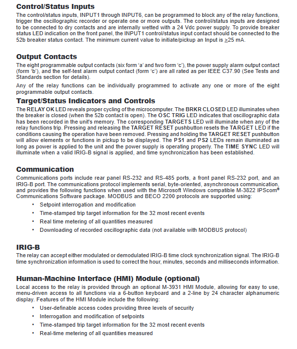
2. Digital input (6-way dry contact)
Internal 24V wet contact, minimum operating current 25mA; can be used for circuit breaker position, protection locking, waveform recording triggering, and external protection access.
3. Programmable outputs (8 channels)
6-way Form A normally open, 2-channel Form C conversion; Free allocation of any protection tripping and alarm; Independent power supply failure, dedicated alarm contact for whole machine self check, contact capacity meets IEEE C37.90 standard.
4. Communication hardware
Front RS232: local computer debugging;
Backplane RS23+two-wire RS485 (optional four wire);
IRIG-B BNC clock synchronization, unified millisecond time scale;
Supports MODBUS and BECO2200 dual industrial protocols;
Remote functions: reading and writing fixed values, real-time measurement, downloading and recording waves, batch control instructions, and querying historical faults.
5. Power supply system
Standard AC/DC wide range power supply: 85~265Vac/80~288Vdc; 24/48V low-voltage DC version is optional; Optional second redundant power supply, with a total power consumption of 20VA and a short-term withstand voltage of 300V for 1 second.
Human machine panel and status indication
Standard LED: device normal, circuit breaker closed, waveform recording trigger, fault target, dual power operation, IRIG-B synchronization indicator light; The Target reset button allows you to view the current startup protection;
Optional M-3931 HMI: 6-button LCD, three-level operation password, on-site viewing of settings, measurements, and fault records;
Optional M-3915 optical module: 24 independent protection action indicator lights, operation and maintenance do not require a computer to quickly locate faults.
Environmental, safety regulations, and mechanical parameters
1. Environmental tolerance
Working temperature -20 ℃~+70 ℃; No condensation at 40 ℃/93% RH; PCB anti mold coating; Passed IEC electrostatic 8kV, 4kV fast transient, IEEE oscillation surge, and 35V/m RF anti-interference tests.
2. Insulation and voltage resistance
Independent circuit 3500Vdc withstand voltage for 1 minute, IRIG-B, communication circuit 1500Vac; The insulation resistance is greater than 40M Ω.
3. Physical dimensions
Standard 19 inch 3U rack: width 48.3cm x height 13.2cm x depth 25.4cm; supports horizontal standard installation and vertical retrofit panels; Net weight 7.7kg, transportation 11.3kg.
4. Terminal specifications
Suitable for 22-12AWG copper wire, different terminals distinguish 8/12 inch pound tightening torque; Only passive dry contacts are allowed to be connected to the switch, and direct external strong current is prohibited.
document supporting drawings
Definition diagram of the backplane terminal of the whole machine;
Typical primary single line diagram for DER distributed power grid connection (PT/CT, interconnection switch wiring);
Secondary control wiring (tripping, alarm, communication, power supply);
Horizontal and vertical rack opening size drawings.