DEIF GPU-3 Synchronous/Asynchronous Generator Integrated Microcomputer Protection Controller
General Product Overview
1.1 Application positioning
The whole machine is equipped with a fully isolated three-phase measurement circuit, which can be used independently or connected to an external PLC. Signal interaction is achieved through digital, analog, and serial communication, and is widely used in land generator sets and ship power stations.
1.2 Display Unit (DU-2)
Standard 3-meter display cable, the display screen can be directly installed on the host or separately installed on the cabinet door;
A single host can expand up to 2 remote display screens, with a maximum communication distance of 200m;
Real time display of measurement values, calculation parameters, alarms, and event records on the screen.
1.3 Self checking function
Periodic automatic self check during power on, with dual prompts of text pop-up and dedicated status relay for faults.
1.4 M-Logic Micro PLC (Free PC Tool)
Supporting free upper software, freely customizable input and output logic, functional mapping, no programming threshold, suitable for personalized control logic.
1.5 Two ways to set parameters
Local menu: password protected;
PC upper software (free download from official website): USB connection, supports online monitoring, parameter upload and download, firmware upgrade.
1.6 Optional synchronization function (G option)
Complete voltage/frequency/phase synchronization closing, automatically exit voltage regulation after closing, and only retain the full set of protection functions.
1.7 Engine control options (M4 hardware board+Y software layout)
Independent processor, independent power supply engine interface board, realizing complete start stop timing of the unit; When the main processor fails, it still has a backup channel for shutdown protection.
Supporting IO resources: 3 multifunctional inputs (wire breakage detection, supporting 4-20mA/Pt100/Pt1000/RMI/0~40VDC), 7 digital inputs, MPU speed acquisition, pre lubrication/starting motor/running coil/stopping coil (with wire breakage monitoring), 4 relays, dual CAN bus (compatible with H7 engine protocol).
1.8 Extended Option System
Divided into two categories: software authorization and hardware plug-in board, hardware in the same slot is mutually exclusive, and can be matched as needed to achieve protection, communication IO、 Speed and voltage regulation expansion.
1.9 Classification Society and Certification
The mainstream classification society has complete ship certification and UL/cUL certification, and the certificates can be found on the DEIF official website.
Standard built-in ANSI full protection function
All functions are standard, covering two major types of faults: generator and busbar, with graded alarms/trips:
Protection Type ANSI Number Classification Quantity Core Description
Generator reverse power 32 level 2 to prevent generator reverse power transmission
Generator overcurrent 50/51 6-level instantaneous+inverse time segmented protection
Voltage dependent overcurrent 51V level 1 low voltage current limiting protection
Anti time overcurrent 51 Class 1 long-term overload protection
Generator overvoltage/undervoltage 59/27 2/3 level abnormal voltage graded action
Generator over frequency/under frequency 81 3/3-stage abnormal speed protection
Bus overvoltage/undervoltage 59/27 3/4 level grid side voltage protection
Bus over/under frequency 81/81 3/4 level power grid frequency protection
Bus voltage imbalance 60 Level 1 three-phase imbalance tripping
Non critical load NEL unloading – Level 3 graded load shedding
Generator overload 32, level 5 active overload protection
Current imbalance 60 1 stage stator three-phase current imbalance
Voltage imbalance 60 Level 1 machine terminal three-phase voltage imbalance
Overexcitation/demagnetization 40/32RV level 1 excitation circuit fault protection
Additional software options can be added for advanced grid protection such as out of step, ROCOF frequency change rate, vector jump, directional overcurrent, zero sequence/negative sequence voltage and current.
Display panel and operation panel
Basic DU-2 display screen: distinguish between four screen layouts: pure protection, parallel only, engine control only, and parallel+engine, with Alarm, Ready, Self check, voltage regulation, and closing status indicator lights;
Expand the operation panel:
AOP-1 (X3): 16 LEDs, 8 custom buttons, up to 1 per display screen;
AOP-2 (X4): 16LED+8 buttons+status relay, up to 5 units per host;
Accessory cables: 1m/3m/6m display cable, 3m USB debugging cable, cross Ethernet communication cable; The sealing gasket option L can upgrade the display screen protection from IP40 to IP54 for marine use (mandatory requirement for ship inspection).
Application scenarios
Single machine generator protection;
Generator+bus synchronous parallel control;
Multi unit parallel power station (load distribution line interconnection, Modbus networking docking with PLC);
Ship multi generator power management system;
Support various power plant solutions ranging from simple single machine to complex multi machine parallel connection.
Classification of complete machine models
Only the three basic models of GPU-3 Marine for marine use:
01: Host+standard 3m display screen; Material number 2912110030-01
02: Bare host without display screen; Material number 2912110030-02
03: Host+display screen+F1 two-way transmission analog output; Material number 2912110030-01
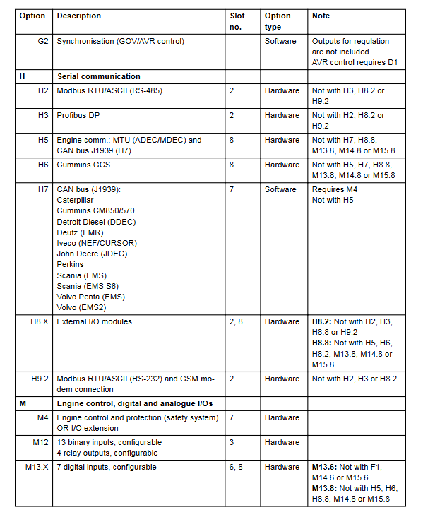
Full range of software and hardware expansion options
(1) Software authorization (no hardware plug in required)
Advanced protection of busbar A: delayed undervoltage, reactive undervoltage, out of step, ROCOF frequency mutation, positive sequence low voltage, directional overcurrent;
C Generator Expansion Protection: Negative/Zero Sequence Voltage and Current, Active and Reactive Power Bidirectional Limitations;
D1 voltage regulation function: combined with E/EF analog output to achieve AVR voltage regulation;
G2 synchronous parallel operation: Unit synchronous closing logic;
Y series interface layout: Y5 only has circuit breaker control, Y7 only has engine control, Y1 parallel+engine complete interface.
(2) Hardware plug-in board (separate slots, mutually exclusive within the same slot)
Slot4 (speed and voltage regulation simulation/relay output)
E1 dual ± 25mA, E2 dual 0 (4) -20mA, EF2 mixed one channel ± 25mA+one channel 4-20mA, EF4 analog+two channel speed control relay, EF5 PWM Carter speed control+analog+voltage regulation relay; D1 authorization is required for AVR voltage regulation.
Slot6/8 IO Expansion
F1 two-way transmission output; M13 multi-channel DI, M14 multi-channel relay, M15 four-way 4-20mA analog input;
Slot2 communication card
H2 Modbus RTU (RS485)、H3 Profibus DP、H9.2 RS232 Modbus; Mutually exclusive and cannot be selected together;
Slot7/8 engine CAN bus
H5 MTU protocol, H6 Cummins GCS, H7 J1939 multi brand diesel engine CAN communication (Caterpillar, Cummins, Volvo, etc.);
Slot10 Ethernet N: Modbus TCP, EtherNet/IP, SMS/email alarm;
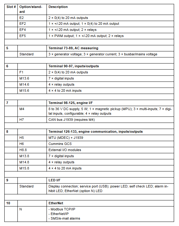
Hardware slot structure
The whole machine has 10 hardware slots, and each slot can only accommodate one hardware option:
Slot1 (standard): power supply 8-36VDC, 5-way relay, 2-channel pulse power output, 5-way DI, status relay; Terminal 1-28
Slot2: External communication H2/H3/H9.2; Terminals 29-36
Slot3: M12 IO extension (13DI+4 relays); Terminals 37-64
Slot4: GOV/AVR analog/relay output E/EF/M14.4; Terminal 65-72
Slot5 (standard): Three phase generator voltage and current, three-phase bus voltage isolation measurement; Terminal 73-89
Slot6: F1/M13.6/M14.6/M15.6 IO Expansion; Terminal 90-97
Slot7 (M4 engine board): independent power supply, MPU speed, multifunctional input, start stop relay H7 CAN; Terminal 98-125
Slot8: H5/H6/H8.8 external IO, M13.8/M14.8/M14.8/M15.8; Terminals 126-133
Slot9: Display screen, USB debugging, status LED;
Slot10: Ethernet N option;
Complete electrical and environmental technical parameters
1. Measurement accuracy
Conventional measurement level 1.0; EF series analog output 4.0 level; Zero sequence/negative sequence protection level 1; The fast overcurrent error is only 3% of the rated current.
2. Environmental conditions
Working temperature: -25~70 ℃, Ethernet version up to 60 ℃, UL certified equipment up to 55 ℃;
Storage: -40~70 ℃; Humidity 97% RH without condensation;
Altitude: ≤ 2000m full range; 2000~4000m needs to be downgraded for use;
3. Measurement circuit
Voltage 100~690VAC (UL limit 600V); CT secondary 1/5A; frequency 30~70Hz; CT continuous 4 times rated, 10 seconds 20 times, 1 second 80 times overload tolerance.
4. Power supply system
Main circuit 1-2 terminals: 8-36VDC, 11W for the whole machine; engine board 98-99 independent 8-36VDC, 5W; Start and drop for 10ms without losing power; The circuit is equipped with a 2A slow melting fuse as standard.
5. IO electrical specifications
Digital input: Bidirectional optocoupler, conducting 8-36VDC, disconnecting<2V;
Multi functional input: 4-20mA, Pt100/1000, resistor, 0~40VDC;
Relay output: 250VAC/30VDC 5A, UL resistive load 2A;
Analog output: isolated type 0/4~20mA, ± 25mA, maximum load 500 Ω;
6. Insulation and voltage resistance
AC voltage circuit 3250V isolation, AC current 2200V, analog/digital IO 550V;
7. Protection action speed
Quick break overcurrent<40ms, emergency stop<200ms, reverse power/voltage imbalance<200ms, frequency drift up to 300ms, ROCOF only 130ms;
8. Machinery and Protection
Host IP20, display IP40 (with gasket IP54); Support rail installation/6 screws for backplate fixation; Plastic UL94 V1 self extinguishing; Meet the IACS vibration and impact standards for ships, and comply with EN61010, UL508, and CE EMC marine specifications.
9. Size and weight
The host measures 230 × 165mm with a thickness of 115mm; the net weight of the host is 1.6kg, and the display screen weighs 0.4kg.
10. Wiring torque
Terminal plug 0.5Nm, display screen 9-pin Sub-D 0.7Nm, Sub-D communication head 0.2Nm; differentiate between AC, DC, and communication cable diameter specifications, UL equipment only allows 60/75 ℃ copper wires.