Installation, Operation, and Maintenance Instructions for Bonfiglioli AS Series Reducer
Technical Information
Equipment identification nameplate
The nameplate includes: equipment model, product code, manufacturing year and month, installation location, speed ratio, and manufacturer’s name. The nameplate must be kept clear; When ordering spare parts or applying for technical support, all information on the nameplate must be provided.
Device description
The AS series reducer is integrated into mechanical equipment and powered by an electric motor; Multi version configuration, suitable for the mechanical, chemical, agricultural, and food industries.
Special safety requirements for ATEX explosion-proof models
Only use synthetic lubricants and fluororubber seals
All external bolts and plugs use thread locking agent
Configure ventilation plug with anti intrusion valve
The AS output shaft is equipped with dual oil seals, while the other shafts are equipped with dust-proof oil seals
The components can withstand the maximum working temperature; External metal free sliding friction; Plastic parts anti-static; Configure irreversible temperature sensor
21/22 Dust area, regularly cleaned to prevent dust accumulation; The active coupling adds sealing to prevent dust accumulation.
compliance
The equipment complies with EU health and safety requirements; The supporting motor complies with the low voltage directive and electromagnetic compatibility directive; Explosion proof models meet ATEX 2014/34/EU, equipment group II; category 2G gas/2D dust; Gas Zone 1, Dust Zone 21; Temperature level T4 (gas)/135 ℃ (dust), some models T3/160 ℃.
Gearbox structure
AS45-AS110 provides two types of structures: foundation installation (AS…/DP) and flange installation (AS…/DF); The document contains exploded exploded part diagrams, showing components such as gears, shafts, bearings, seals, and housings.
Operational restrictions and allowed environment
Only allowed for industrial use as specified in the design; Modification of installation form and equipment version must be authorized by the manufacturer, otherwise ATEX explosion-proof certification will become invalid. Prohibited environment: strong corrosion/abrasion, steam, smoke, dust; Direct contact with bulk food; Without permission, it shall not be used in explosive hazardous environments. The heat dissipation will be affected by the size of the installation chamber and the surrounding heat sources.
Allowable temperature limit
Parameter synthetic oil mineral oil
Minimum working environment temperature -30 ℃ -10 ℃
Maximum working environment temperature+50 ℃+40 ℃
Storage environment temperature -40~+50 ℃ -10~+50 ℃
Continuous maximum surface temperature of the shell+100 ℃+100 ℃
Continuous maximum oil temperature of lubricating oil+95 ℃+95 ℃
Note: Long term operation at 80-95 ℃ is not recommended; It is recommended to gradually increase the speed when starting at full load.
Storage requirements
Place on a stable base; Prohibit storage in open air and high humidity environments; Avoid internal condensation caused by drastic temperature changes; Prohibit direct landing.
Apply rust inhibitor (such as Shell Ensis SX) to the exposed metal surface during processing, and regularly reapply.
Storage>6 months: Apply rust inhibitor; Add lubricating oil and replace the vent plug with a plug (except for lifetime lubrication models).
Storage>1 year: The lifespan of bearing grease decreases, and synthetic grease must be used.
Re enable: Clean the anti rust coating and ensure that the solvent does not come into contact with the oil seal; When the storage oil is incompatible with the working oil, thoroughly clean the interior.
Install
During the installation phase, it is necessary to consider the space for later maintenance and repair; Installation to avoid impact; Please also refer to the accompanying motor manual.
Installation steps of reducer
If the storage oil is not working oil, drain the oil and flush the inside; Remove the anti rust coating from the packaging and avoid the oil seal with solvents.
Verify that the nameplate parameters are consistent with the order; Confirm that the rigidity of the installation base is sufficient to withstand the weight and working load; Configure hydraulic couplings and torque limiters for impact and overload conditions.
Power off the entire machine to prevent accidental startup; Ensure that the joint surface is flat and the axis is aligned; Install rotating component protection.
Corrosion environment consulting firm; Use anti micro dynamic corrosion lubricant for key connection pairs; Clean the friction coupling surface and do not apply lubricating paste.
Output solid shaft coupling internal hole ISO H7 tolerance; Outdoor installation with sunshade and rain cover to ensure ventilation. The shell is reliably grounded.
When the surface temperature may exceed the standard, protective measures should be installed or “IEC 60417 High Temperature Warning Signs” should be posted.
Fixed in place: use all fixed holes; Replace the transport blind plug with a vent plug; Tighten the bolts according to the torque specified in the manual; Tighten the plug according to the torque; Do not use bolts higher than grade 8.8 for aluminum shells.
Add lubricating oil and confirm the oil level according to the window/oil level hole. The manual provides a complete bolt torque table and plug torque table.
Solid input/output shaft
Do not strike external components with a hammer during assembly; Hollow spline/keyway output shaft assembly, equipped with pull rod bolts and spacers (non supplied parts), refer to the drawing.
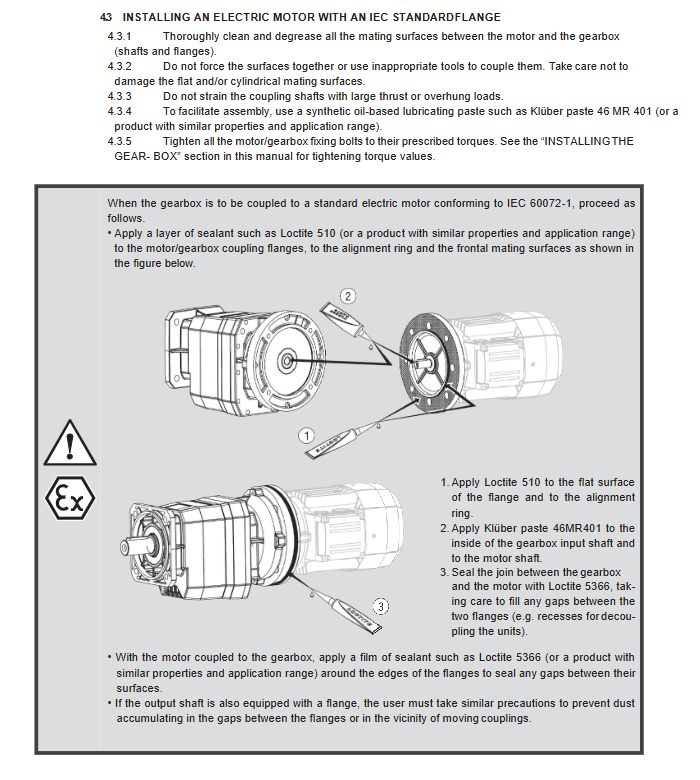
IEC standard flange motor installation
Thoroughly remove oil and clean the mating surfaces of the motor and reducer flanges; Forced assembly is prohibited to avoid damaging the mating surface.
Avoid excessive axial thrust and cantilever load on the coupling; Use lubricating paste on the mating surface; Apply Loctite 510 sealant to the flange and seal the outer ring gap with Loctite 5366.
Tighten the bolts according to the specified torque.
Lubrication Details
The oil level inspection must be carried out in the actual working installation posture; Use a 25 μ m filter screen for refueling; There is overflow in the middle of the oil level reference mirror, the oil dipstick marking, or the oil level hole.
AS45-AS100 can be equipped with oil (LO option) at the factory, and comes with a transport plug. The ventilation plug can be replaced on site. The fuel gauge is for reference only, and the final oil level window shall prevail; New machine first maintenance 500 hours oil change. Recommended oil products ALPHASYN PG320 and MOBIL GLYGOYLE HE320.
Installation interface size
Provide all installation posture diagrams B3/B5/B6/B7/B51/B52/B53/V1/V3/V5/V6; Distinguish the positions of the vent plug, oil level plug, and drain plug.
Output flange: Provide the diameter of each specification’s flange, tolerance f7 (reducer)/H8 (mating parts), bolt distribution circle, and flange outer diameter.
Input interface and output shaft size: output shaft diameter tolerance h6, keyway h9.
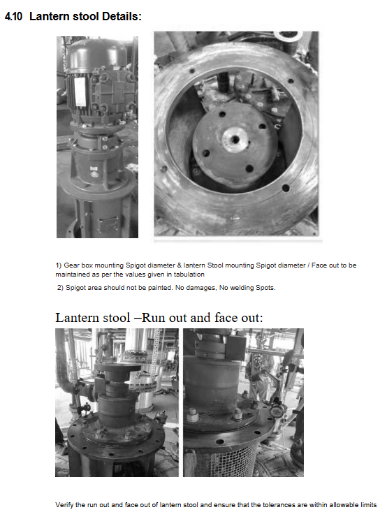
Mid bracket (Lantern stool): The stopper cannot be painted and there is no damage to the welding point; Verify the end face runout and radial runout.
Couplings: Regularly check coaxiality and radial axial offset; Check the key, inner hole tolerance, and bolt tightening.
Noise and vibration acceptance
Noise: The noise level at a distance of 1 meter is ≤ 85dBA, and the judgment of abnormal noise is unqualified.
Vibration: Provide the RMS qualified range of vibration speed based on the rotational speed.
Motor details
Test noise and vibration separately before motor assembly; The motor stopper should be undamaged and free from paint; The motor supports two wiring methods: star (STAR) and delta (DELTA).
put into operation
Confirmation items before commissioning:
The whole machine complies with mechanical instructions; The installation posture of the reducer should be consistent with the nameplate, and non-standard angles must be approved by the manufacturer. The shaft installation allows for a deviation of ± 5 °.
The power supply complies with EN60204-1, the grounding is reliable, and the voltage fluctuation is within ± 10%.
The oil level is normal and there is no leakage; Transport dismantled components for restoration; Reinstall the protective device.
The thickness of dust accumulation in explosion-proof environments shall not exceed 5mm.
Startup inspection: no abnormal noise or vibration; Run for 100 hours to recheck the torque of all connecting bolts. Temperature measurement: The temperature measurement is taken at the junction of the reducer and motor, as well as at the location of ventilation obstruction; Maximum temperature reached after 3 hours of full load; The temperature rise Δ T should not exceed the ambient temperature+75 ℃. If it exceeds the tolerance, immediately stop the machine and contact the manufacturer.
Maintain
Maintenance personnel must be professional; Non manufacturer/authorized service repairs during the warranty period will directly result in the expiration of the warranty. Cut off the power supply, lock and tag the equipment, and allow it to cool down thoroughly before starting work.
Prioritize the use of original spare parts for maintenance; It is recommended to replace bearings in pairs; Complete the repair and replace all sealing gaskets; Apply lubricating grease before installing the oil seal; Fill synthetic grease in the middle of the double oil seal.
Long term idle equipment: run at least once a month; Otherwise, perform rust prevention protection or fill with oil.
Strict environmental protection disposal of waste; Disassemble and reassemble the thread, then reapply the thread locking adhesive.
Operational efficiency check
Regular dust cleaning; Monitor noise and vibration; Check the current and voltage of the motor; Check the friction plate wear of the brake motor; Check for seal leakage; Monitor the temperature of the shell; Check for corrosion and deformation of bolts.
Regular maintenance cycle
Oil change cycle: depends on the oil temperature. Mineral oil 8000-2000 hours; Synthesize PAO/PAG oil for 25000-12500 hours. Change the oil at the beginning of the new machine for 500 hours. It is not recommended to operate continuously at an oil temperature of 80-95 ℃.
Inspection items: 24-hour noise and vibration; 720h oil level; 2000-4000h bolt tightening; replace external oil seal every 5000 hours; Perform major repairs under 5000 hours of rated torque conditions; The overhaul cycle is adjusted based on the ratio of actual torque output to rated torque.
Explosion proof area 21/22: Regular cleaning, dust thickness not exceeding 5mm.
Regular temperature measurement: measure the temperature rise of the shell every 100 hours or two weeks; Check for oil level leakage every 1000 hours; Check the lining of the reaction arm after 3000 hours; Replace synthetic oil and lubricating grease after 5000 hours.
Oil change operation
Shutdown cooling; Oil release; Clean the drain plug magnet; Fill the designated brand of lubricating oil to maintain the actual installation posture of the equipment; Apply sealant to the thread of the plug; Take protective measures when dealing with waste oil. If a leak is found, first troubleshoot and then replenish the oil.
clean
Prohibit high-pressure water flushing; Prohibit the use of solvents that are incompatible with the material of the equipment.
Dismantling
Dismantling of IEC flange motor
After loosening the bolt, the motor still gets stuck. Do not use a pry bar to forcefully pry it; Tap the fan end of the drive shaft and use an impact extractor to remove the motor to avoid damaging the flange mating surface.
Troubleshooting
Troubleshooting plan for the cause of the malfunction
The bearing temperature is too high and the oil level is too low; Oil aging; Oil replenishment for damaged bearings; Change the oil; Authorized workshop maintenance
The overall operating temperature is high and the oil level is too high; Oil aging; Oil pollution correction oil level; Change the oil; oil change
Abnormal operating noise and gear damage; Excessive bearing clearance; Bearing wear; Overload; Contact authorized workshop for oil pollution; Reduce load; Change the engine oil
There is abnormal noise in the installation position, and the fixing bolts are loose; Bolt damage should be tightened according to the prescribed torque; Replace bolts
Oil leakage level is too high; Damaged shell seal; Gasket aging correction oil level; Authorized workshop maintenance
Difficulty in rotating the gearbox or failure to rotate due to high oil viscosity; The oil level is too high; Replace the adapter oil when the load is too large; Correct the oil level; Redesign the transmission
Motor running, output shaft not rotating, gear damaged. Contact authorized repair workshop
Tip: Some of the faults are caused by the supporting host equipment, and it is necessary to investigate the host at the same time.