Bonfiglioli EM-ENC-03 Expansion Module
Bonfiglioli Vectron EM-ENC-03 Expansion Module Operation Manual, compatible with ACT and ACU series 230V/400V frequency converters, version 06/05; The module is an optional hardware that adds two major functions to the frequency converter: CAN system bus interface and second incremental encoder speed sensor input. ACU supports the entire series, while ACT frequency converter requires software version ≥ 4.1.0. The module must be installed in the bottom slot of the frequency converter after power off.
Introduction to EM-ENC-03 module
The module provides two sets of hardware interfaces:
CAN high-speed system bus (ISO-DIS 11898), with a maximum baud rate of 1M;
The second incremental encoder speed sensor input.
Important limitation: If another CAN controller option (CM-CAN) is installed simultaneously with the frequency converter, the CAN bus interface of EM-ENC-03 will be automatically disabled.
Mechanical and Electrical Installation
3.1 Mechanical Installation
The frequency converter is completely powered off and waiting for the capacitor to discharge;
Remove the lower cover plate of the frequency converter and insert the EM-ENC-03 module into the bottom slot;
Caution: Do not touch the PCB circuit board on the back of the module, static electricity can damage hardware;
Restore the lower cover plate; The module is automatically ready after power on.
3.2 Terminal Definition
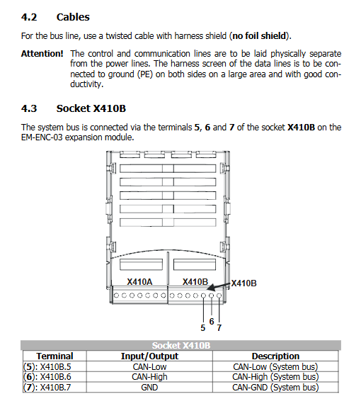
The module has two terminal sockets X410A and X410B, with a wiring torque of 0.2-0.3Nm.
X410A (encoder interface)
Terminal signal
1 A+
2 A‑
3 B+
4 B‑
6 GND
Electrical specifications: maximum input frequency 300kHz; Supports TTL RS422 (5V push-pull) and HTL single ended 24V encoder. Dial S3: Encoder 150 Ω terminal resistance, only 5V differential encoder is turned on; The 24V single ended encoder must be turned off; The two dialing codes for S3 must be set to be the same, otherwise it will damage the hardware.
X410B (CAN system bus)
Terminal signal
5 CAN‑Low
6 CAN‑High
7 GND
CAN bus dialing S1/S2: Bus terminal resistance
S1=ON, S2=OFF: ordinary passive terminal;
S1=ON, S2=ON: Active terminal (only one node in the network is allowed to turn on the active terminal, the rest of the nodes are passive); All products are turned off by default at the factory.
3.3 Wiring Requirements
CAN bus uses braided shielded twisted pair cables (do not use aluminum foil shielded wires); Communication cables and power cables are physically laid separately; Both ends of the shielding layer are reliably grounded to PE over a large area.
CAN system bus interface (core function)
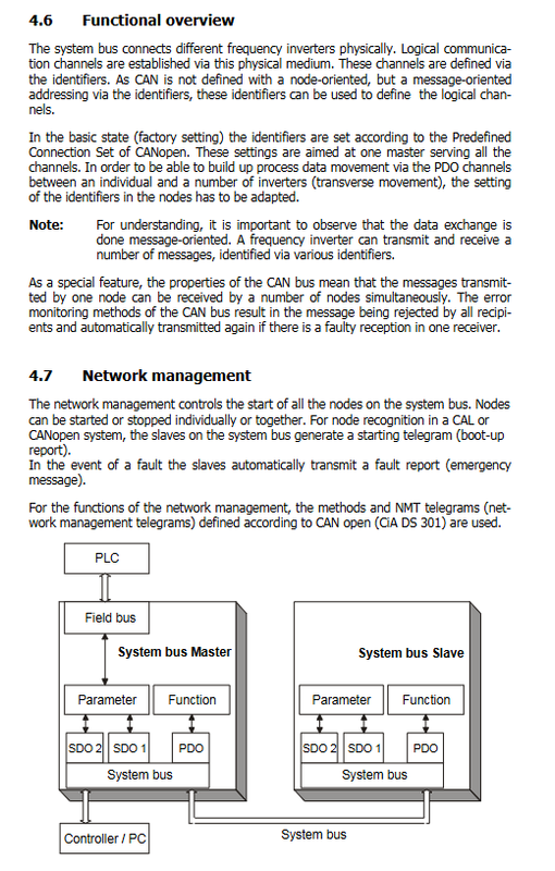
The bus topology is a linear CANopen bus, supporting a maximum of 63 slave nodes and 1 master node.
4.1 Basic parameter settings
Node address parameter 900 Node ID
-1: Bus shutdown (factory)
0: This machine serves as the bus master station (the entire network can only have one master station)
1-63: Slave node ID, all network IDs must be unique
Baud rate parameter 903 Baud Rate: The baud rate of all nodes must be consistent, and the corresponding relationship between baud rate and maximum bus length is:
Maximum cable length for baud rate
50kbit/s 1000m
100kbit/s 800m
125kbit/s 500m
250kbit/s 250m
500kbit/s 100m
1000kbit/s 25m
Not recommended below 50k due to insufficient throughput.
4.2 Bus Communication Model
Compatible with CANopen standard, divided into SDO parameter channel and PDO process data channel; Supports two working modes: master station and slave station.
SDO channel (Service Data Object, Read/Write Parameters) 2 SDOs per frequency converter:
SDO1: Used for reading and writing parameters of PLC/main station frequency converter;
SDO2: Specially designed for use with upper level visualization tools, can be parameter disabled (parameter 923). Using the Expedited Fast SDO protocol, only uint/int/long type parameters are supported, and string parameters cannot be transmitted. All slave frequency converter parameters on the bus can be indirectly accessed through the Profibus DP/RS232 485 (Vectron bus) of the main frequency converter.
PDO channel (process data object, real-time process data) Each frequency converter receives 3 sets of RxPDO and sends 3 sets of TxPDO, with each set of PDO fixed with 8 bytes of data.
Operation mode: time triggered, SYNC synchronization message triggered; Can be closed;
Timeout monitoring: Parameters 939 and 941-945 set timeout time, 0=turn off monitoring; Super time fault F2200-F2203;
Virtual links: This device does not use standard CANopen PDO mapping objects and uses a source number mechanism. TxPDO: Fill in the source number and send the internal signal of the frequency converter to the transmission message; RxPDO: The received message is mapped to an internal source number, which is read by other functions of the frequency converter; Support mixing multiple data types such as boolean, uint/int, and long to fill 8-byte PDO.
4.3 Main Station Function (Node-ID=0)
NMT network management: Send NMT messages to control the status of all slave stations: Pre Operational, Operational Running, Stopped;
Parameter 904 Boot Up Delay: Power on startup delay, 3500-50000ms;
Generate SYNC synchronization message: parameters 918 SYNC Identifier, 919 SYNC Time, time 0 represents not sending SYNC;
Handling emergency messages from the slave station Emergency Message: Parameter 989 Emergency Reaction configuration fault response: 0=direct fault shutdown of the master station; 1=Alarm only;
Client SDO client, access all slave parameters.
4.4 Slave Function (Node-ID=1-63)
Power on and send Boot up startup message; Receive NMT instructions to switch working states;
Receive SYNC message to synchronize RxPDO and trigger TxPDO transmission;
Send an Emergency message when a fault occurs, and send a reset emergency message when the fault is cleared;
Server‑SDO, Respond to requests for read and write parameters from the main station.
4.5 Bus status monitoring parameters
978 Node State: Node State 1 Pre operation/2 Running/3 Stopping
979 CAN State: Physical layer status 1 Normal/2 Warning/3 BUS OFF; When a BUS-OFF fault occurs with F2210, the controller automatically restarts.
4.6 Bus Planning Tool
The manual provides three planning documents (available on CD)
Kbl.doc: Communication Relationship Definition Table;
Vvk.doc: Virtual Link Planning Table;
Load_Systembus.xls: Bus load calculation table.
Bus load recommendation: ≤ 80%,>90% unavailable, message retransmission margin must be reserved.
Encoder inputs (speed sensor 2)
X410A second incremental encoder interface, used for speed measurement, can be used as a speed closed-loop actual speed feedback source, or as a frequency setpoint source. Key parameters:
493 Operation mode speed sensor 2: Encoder working mode, 4x, reverse 4x;
494 Division Marks Speed Sensor2: Encoder line count, 1-8192, factory 1024;
495 Level: Level selection: 0=5V push-pull RS422; 2=24V single ended HTL;
766 Actual Speed Source: Selection of speed closed-loop feedback source, option 2 represents the use of the encoder in this module;
Actual value reading: 219 (encoder 2 frequency Hz), 220 (encoder 2 speed rpm).
Calculation formula limitation: Input maximum frequency of 300kHz; Ensure that the signal is ≥ 500Hz at low speeds to ensure measurement accuracy.
Parameter List
Divided into actual value menu VAL and parameter menu PARA;
VAL:219、 Actual value of 220 encoder; 978, 979 bus status;
PARA: Encoder parameters 493-495; Speed source 766; A large number of system bus parameters (starting from 900, node ID, baud rate, PDO mapping, virtual link parameters, etc.).
Note: Most bus parameters are not visible on panel KP500 and require VPlus software to import XPI configuration files to access.
Fault alarms (related to EM-ENC-03)
Encoder related faults
F30: Speed sensor signal fault;
F31: Missing one encoder channel;
F32: Encoder phase sequence direction error.
CAN bus malfunction
F21nn: There is a fault in the slave station nn on the bus;
F2200: SYNC message timeout;
F2201-03: RXPDO1-3 received timeout;
F2210: CAN hardware BUS OFF.